
According to IEEE standards, an Antenna is a metallic device (rod/wire) radiating or receiving radio waves.
Functions of Antenna:
1. The antenna is acting as a transducer.
2. Antenna is an impedance-matching device.
3. The antenna can radiate EM energy in a particular direction.
4. An antenna transducer between a directed wave and free space.
5. The antenna acts as a remote-sensitive device.
Antennas are classified based on
1. Physical structure of Antenna.
2. Frequency Range of Antenna.
Table of Contents
Antenna Parameters
1. Radiation Pattern:
- The antenna radiation pattern can be expressed in terms of field Antenna pattern and radiation intensity
- Field Pattern: It is a graphical representation of the electrical field strength of electromagnetic waves at all the points equidistant from the antenna.
- The polar graph is used to represent the radiation pattern more precisely. It is a two-dimensional graph.
- The radiation patterns can be characterized by two primary planes, the E-plane and the H-plane.
- One of the magnitude of the normalized field strength concerning and as a constant plain is called an E-plain.
- When the normalized field strength is plotted concerning for is constant, it is known as the H-plain pattern.
- For a dipole, the Omni direction pattern can be represented by E-plain.
- The field pattern in general can be expressed in a normalized direction
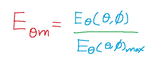
The radiation or field pattern is mainly dependent on the current distribution.
Power Pattern:
Suppose the radiation pattern is expressed in terms of power. At point P, power is distributed radially outwards.
Therefore it is given by =E/H=neeta

2. Half Power Beamwidth:
Half power beam width is the angular separation expressed in a decrease on the main lobe between two points where the power becomes half. Half power beam width is also known as 3 dB beam width.
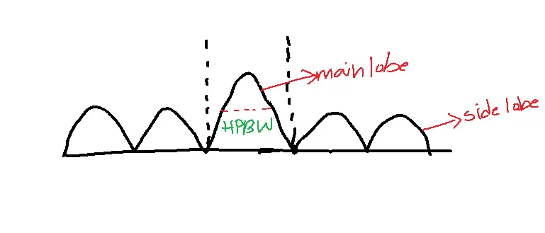
The angular separation between the two first null points next to such an angular beam width is known as full null beam width.
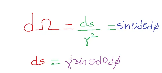
The radian is a measure of an angle within a two-dimensional plane.
While the steradian is used to quantify the size of a cone-like region in three-dimensional space.
Steradian can be defined as dΩ=Area/r2.
3. Beam Area:
Beam area/solid angle can be defined as the integral of normalized power pattern over space and is expressed as ΩA of steradians.
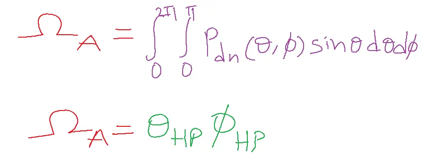
The beam area is described as the angle subtended at half power points.
4. Radiation Intensity:
Radiation Intensity is defined as the ratio of power per unit solid angle and is denoted by U.
U=R2Prad
U=dPr/dΩ w/sr
5. Beam Efficiency:
Beam efficiency is defined as the ratio of power transmitted[received] within the core angle to the energy transmitted or received by the antenna.
Beam Efficiency is defined as the ratio of the main beam area to the total beam area.
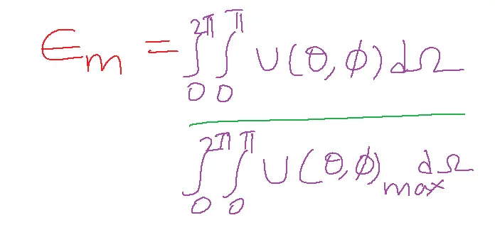
En+Em=1.
Beam efficiency:
6. Antenna Gain:
The ability of the antenna to transmit to a particular distance to absorb the radiation from a certain distance is defined as the antenna gain.
Antenna gain is of two types:
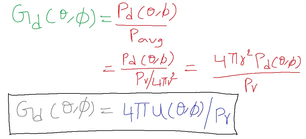
i. Directive Gain(Gd)
ii. Power Gain(Gp)
- The Directive Gain is defined as the ratio of radiation intensity of the antenna in a particular direction to the average power.
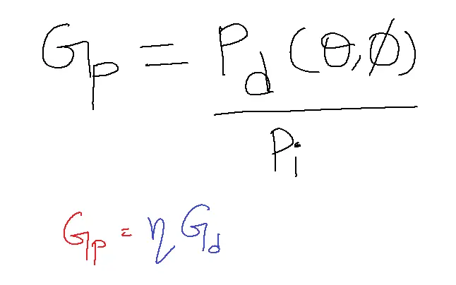
- Power gain is the ratio of the power density of the antenna in a particular direction to the total input power.
- n lies between 0 to 1. And it is known as efficiency.
- Power gain is the relative power density transmitted by the test antenna in a given direction to the power radiated by the isotropic radiator.
7. Directivity:
- Directivity is a measure of maximum directive gain in a given direction.
- Directivity is the radiation intensity in a given direction to the average radiation intensity of a test antenna.
- Directivity is also defined as the maximum radiation intensity of the test antenna to the isotropic radiator.
- Directivity can be defined as power radiated by the test antenna to the energy emitted by the isotropic radiator.
- The difference between directivity and directive gain lies in the distribution of radiator power in space whereas the directivity depends on the beam solid angle of the antenna.
- While the directive gain of an antenna can range from zero to infinity, its directivity is always greater than or equal to one.
The Resolution is half the value of the full null beam width.
N=FNBW/2=HPBW
N=4π/ΩA
D [approximately equal to]= 4π/ΩA
N=D for lossless antenna.
8. Front-to-Back Ratio(FBR):
It is the ratio of the signal radiated in the desired direction to the radiation in the opposite direction.
The front-to-back Back Ratio value must be high to transmit the signal in the desired directions.
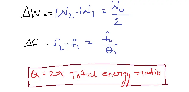
9. Antenna Bandwidth:
Antenna bandwidth is the band of frequencies in which the antenna effectiveness is confirmed within a specified standard.
Hence, a decrease in the Q value directly corresponds to an increase in bandwidth.
Radiation Mechanism:
Radiation is the phenomenon of the transfer of electromagnetic energy into the surrounding medium.
Let a charge of 1 coulomb is traveling a distance of 1m within 1 second, we can define the equation of radiation as
L.I’=Lqv. Am/sec
Therefore, to have radiation two conditions must be met:
i. Current must be time-varying
ii. Charge must be accelerated
Time harmonics represent the current whereas transients are used to stand for the charges.
Half wave Dipole:
- The optimal length of an antenna is a function of the operating frequency, which is determined by the wavelength of the signals it’s intended to transmit or receive.
- With the current distribution over the antenna is about half the wavelength then the antenna is tamed as half wave dipole.
- A mathematical or graphical representation of the radiation property of any antenna as a function of special coordinates is known as a Radiation Pattern.
- By examining the antenna’s parameters, we can gain insights into its operational performance and the distinct features of its radiation patterns.
Antenna Aperture:
1. Effective Aperture:
- Effective Aperture is the ratio of the received power by the load resistance to the underlying vector or average power density.
Ae= Power received by the load/average power=w/(w/m2)
Ac=w/P=I2rmsRL/Pavg
Irms=V/Z=V.V/(Ra+jxa)(Rl+jxl)
Ae=V2/4Rr.Pavg
Radiation Resistance:
Radiation resistance is a theoretical concept representing the equivalent resistance that, if connected in series in the circuit, would dissipate the same amount of power as the antenna radiates.
Radiation resistance depends upon surrounding areas, material, and Antenna configuration
2. Scattering Aperture: Scattering Aperture is the ratio of power received by radioresistance to the average power.
3. Loss Aperture: Loss Aperture is the ratio of power received by the loss resistance to average power.
4. Collecting Aperture: The collecting aperture of an antenna is determined by the combined effects of its effective aperture, scattering aperture, and loss aperture.
Ac=Ae+As+AL
= I2rms(RL+Rr+Re)/Pavg
5. Physical Aperture: A physical Aperture is an actual cross-section that can radiate or receive physically.
Effective Length or Effective Height:
The dimensions of the housing structure constrain an antenna’s physical length. However, the current distribution along its length primarily determines its effective length, which is more relevant to performance.
Effective length can also be expressed as the normalized average current, calculated by dividing the average current by the antenna’s physical extent.
For transmission case: The effective height can be defined as the length of the imaginary antenna carrying a peak current of IR, which will produce the same electric field intensity at a given distance as that of an actual antenna.
For the receiving case: The effective length can be defined as the ratio of voltage induced across the open-circuited terminals of the antenna by the incident electric field intensity.
The antenna temperature is a combination of terminal resistance and sky resistance.
TA=Tr+Ts s-flux density
According to Nyquist rate criteria,
T= KTr
PαT P=KTr
P=KTAB TA=SAC/K
For practical antennas, the system noise power is given by
Ps=K(Ts+Tr)B
Ps=TsysB watts
The relation between noise figure and signal-to-noise ratio:
F=1+(Te/T0)
Te – effective temperature
Tr – room temperature
Antenna Efficiency:
Antenna efficiency is the ratio of power radiated to the total input power.
n(Neeta)=power radiated/Pi
=Irms2Rr/ Irms2(Rr+RL)
n= Rr/ Rr+RL
Polarization:
- Polarization of the antenna refers to the locus of the electric field vector in a given plane.
- An electric field with a single component indicates a linearly polarized wave.[vertical or horizontal].
- If the electric field vector contains two components in different directions E0x=Escos(wtx)
- E0y= Escos(wt-y)
- If the phase angle or multiples of ±nπ it is also linearly polarized. The difference is multiples of π/2 that leads to circular polarization.
- The orientation of the tip of the electric field vector will be either clockwise or anti-clockwise (LHCP) or (RHCP).
Problems Related to Antenna Parameters:
1. An antenna has a loss resistance of 10Ω, a Power gain of 20, directive gain of 22. Calculate its radiation resistance.
Sol: Gp=20, GD=22
RL=10, Rr=?
Gp=n GD
n=Rr/ Rr+ RL
Rr=100 ohm
2. Calculate the current drawn by an antenna with a radiation resistance of 300 ohms when radiating 1000 watts.
Sol: W=I2R
W=100 watts
Rr=300 ohm
I2=100/300
I=1.825
3. An antenna exhibits a main lobe with half-power beam widths (HPBW) of 90° in the horizontal plane (H-plane) and 20° in the vertical plane (E-plane). Estimate the approximate directivity of this antenna and express the result in decibels (dB).
Sol: D=41253/200X 900=40.25
4. Express E(theta)=cos(theta).cos2(theta). Express in FNBW
Solution:
FNBW=2 X 45 DEGREES= 90 DEGREES
HPBW=45 DEGREES
Related FAQs
Q1. What are the key parameters of an antenna?
- The key parameters of an antenna include gain, directivity, beamwidth, polarization, impedance, bandwidth, efficiency, radiation pattern, and VSWR (Voltage Standing Wave Ratio).
- Understanding these parameters is crucial for selecting the right antenna for a specific application.
Q2. What is antenna gain and how is it measured?
- Antenna gain indicates an antenna’s ability to direct radio waves in a specific direction compared to a reference antenna, usually an isotropic radiator.
- It is measured in decibels (dBi) and indicates the antenna’s power amplification relative to the reference.
Q3. How does antenna polarization affect communication?
- Antenna polarization plays a critical role in communication. Antennas must have matching polarization for optimal signal reception.
- Mismatched polarization can result in significant signal loss or complete signal drop.
Q4. What is VSWR and why is it important for antenna performance?
- VSWR measures the reflection of power back to the transmitter due to impedance mismatches between the antenna and the transmission line.
- A high VSWR indicates inefficient power transfer, leading to signal loss and potential damage to the transmitter.
Q5. How do I choose the right antenna for my specific application?
- Choosing the right antenna involves considering several factors, including:
- Frequency: The operating frequency of an antenna directly influences its type and size.
- Range: The desired range determines the antenna’s gain and directivity requirements.
- Application: The intended use, such as Wi-Fi, cellular, or satellite communication, influences the antenna’s design and features.
- Environment: The environment where the antenna will be installed, indoors or outdoors, can affect its performance.