
- An operational Amplifier is a high gain direct coupled amplifier consisting of two differential amplifiers, a level translator, and an output stage.
- An operational amplifier is also called a linear integrated circuit.
- The operational amplifier is a multi-terminal device with a complicated internal structure. It’s a high-gain amplifier with direct coupling. It is capable of amplifying DC and AC signals. Many mathematical operations, including addition, subtraction, differentiation, integration, logarithmic, and antilog operations are executed inside the op-amp. Due to its use in performing mathematical operations, it has been given the name operational amplifier.
- An operational amplifier is used to construct any mathematical operator. (Adder/Subtractor/Multiplier/Divider circuits).
- The IC version of op-amp uses BJTs and FET is fabricated along with the other supporting components on a single semiconductor chip.
- The advantages are low cost, small size, versatility, and flexibility.
Table of Contents
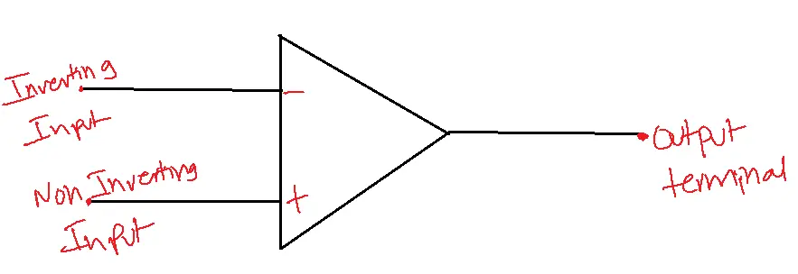
Operating symbol:
Temperature ranges for operational amplifier:
1. Military temperature range – -550 C to 1250C
2. Industrial temperature range – -200C to 850C
3. Commercial temperature range – 00C to 700C
Operational amplifier used in various companies:
- Fair child – uA, uAF
- National Semifield – LM, LH, LF, TBA
- Motorola – MC, MFC
Ideal operational amplifier:
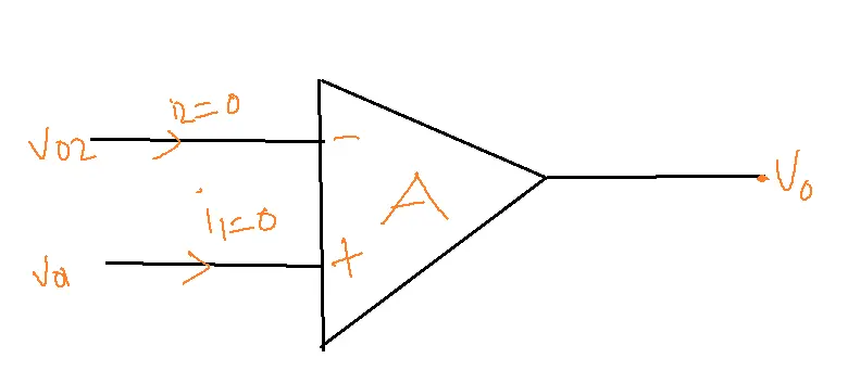
V0 = AoL.Vd
- V1 = positive, V01 = A.V1
- V2 =negative, V02 = A.V2
- Open loop voltage gain is infinity.
- A02=infinity, Vid=V0/A = 0.
- Input impedance is infinite, with no loading problems.
- Since its output impedance is zero, an endless number of additional devices can be driven by it. R0=0.
- Off-set voltages are Rc output = 0 if V1 and V2 = 0.
- Bandwidth is infinity so any frequency signal from 0 Hz can be amplified without attenuation.
- The common mode rejection ratio is infinity. The slew rate is infinity, so the output voltage changes.
Practical operational amplifier:
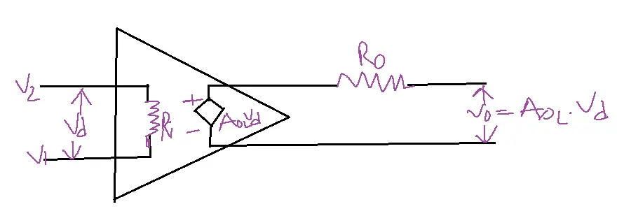
1. AoL≠[large] AoL is open loop gain.
2. Zin ≠ [range of megha ohms]
3. Ro≠ usually few 100 ohms
4. Bandwidth is finite.
5. Offset value has a finite value.
6. Offset values change.
7. Offset values change with temperature change.
Inverting Amplifier configuration of operational amplifier:
The amplifier in which the output is inverted means having a 180-degree phase shift.
Vo = Aoc(V1-V2)
V1 = 0
V2 = Vin
Non inverting amplifier:
Vi = Vin
V2 = 0
Vo = AoLVin
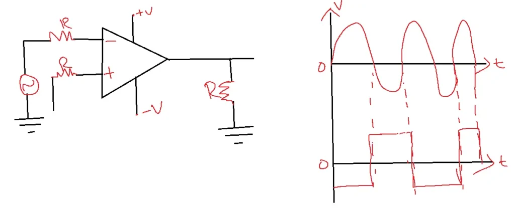
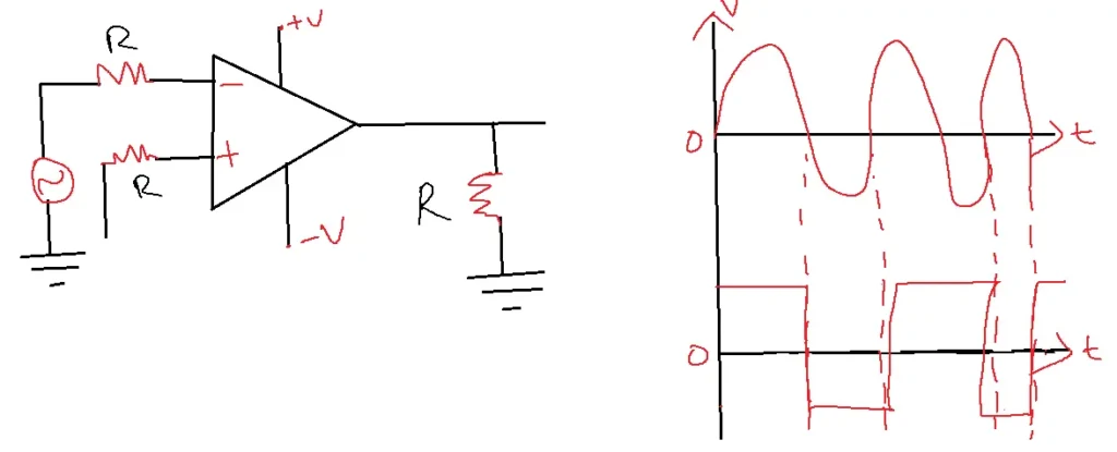
Differential Amplifier:
V= AoLVd = AoL(V1-V2) = AoL(Vin1 – Vin2)
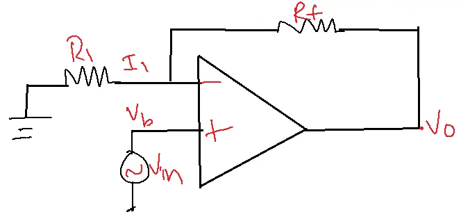
Inverting Amplifier configuration of Op Amp using a closed loop:
RL = Ro
Rin = R1
V0 = -(RB/R1) Vin
Aec = -RB/R1
Non-Inverting Amplifier using a closed loop:
Vo = Vin[1+Rf/R1]
ACL = 1+(Rf/R1)
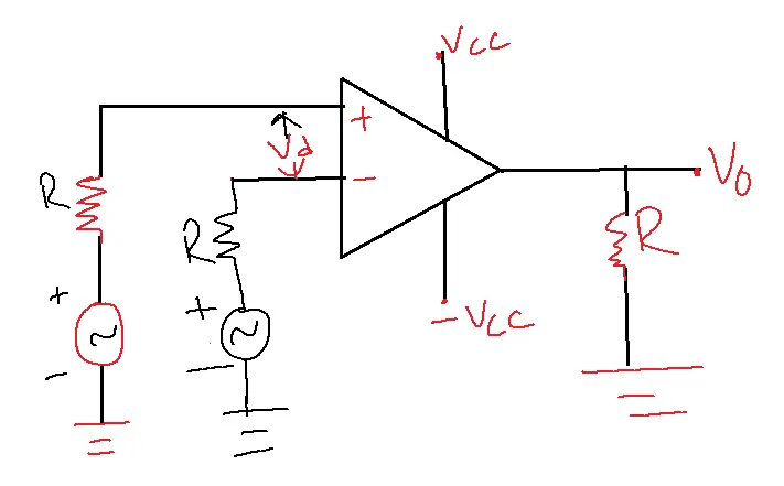
Differential Amplifier using a closed loop:
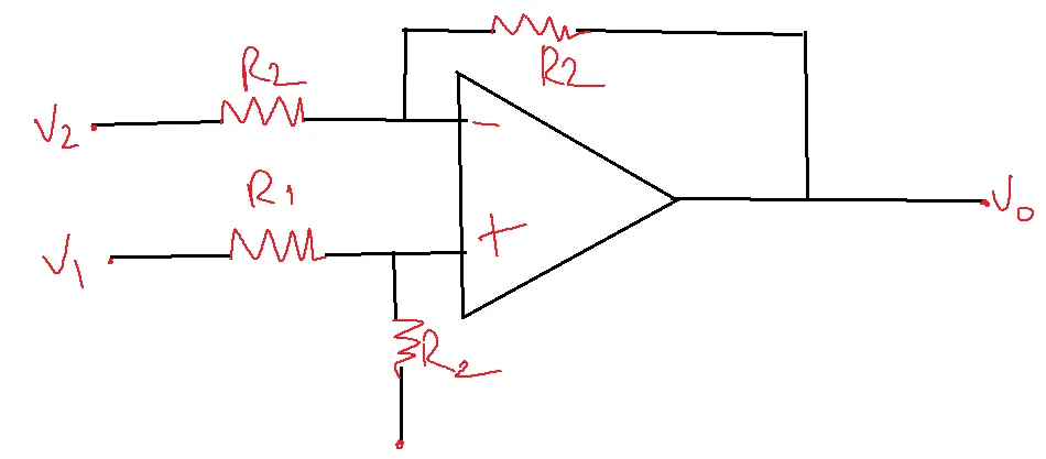
V0 = (R2/R1)(V1-V2)
Operational Amplifier Characteristics:
There are 2 types:
1. AC Characteristics
2. DC characteristics
DC characteristics of Op Amp:
1. Input biased current(IB)
2. Input offset current(Iio)
3. Input offset voltage(Vio)
4. Thermal drift – It can be avoided by providing cool air.
Common Mode Rejection Ratio:
The operational amplifier taken in differential mode having the input voltages v1 and V2 are applied if the input combinations are applied as shown V1 =100 µV and V2 = 90 µV
V1 = 1000 µV and V2 = 990 µV
Since the outputs will not be equal even though the difference Vd is equal in all scenarios, it can be concluded that an op-amp’s output depends on differential voltage, and the average value of applied inputs, is known as a common mode signal.
VCM = V1 + V2/2
V1→A1V1
V2→A2V2
V1 = VCM + (Vd/2)
V2 = VCM – (Vd/2)
Common mode rejection ratio CMRR =Vcm/VD
CMRR = 70dB à typical value.
Common mode rejection ratio CMRR ADm/ACM
AC characteristics of an operational amplifier include frequency response and frequency compensation of an operational amplifier.
A= Aoc/square root of 2. It is -3dB.
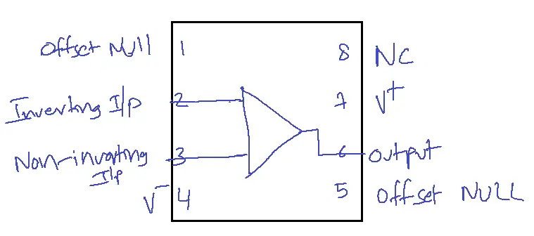
Operational Amplifier features:
1. An Operational amplifier is axed for a circle range of analog applications.
2. 741 is an internally frequency-compensated op-amp.
3. 741 is a monolith IC fabricated cursing planner processor.
4. SC protection is used.
5. No latch-up problem.
6. Lower power consumption.
7. Offset null capability
8. The supply voltage required is ±18V.
Typical values of IC741:
1. It is an offset voltage.
2. Input offset current -20nA.
3. Input biased current is -20nA to -80nA.
4. CMRR – max of 70dB to 90 dB.
5. Input impedance 1M to 2M ohm.
6. Bandwidth 0.437MHz
7. Input resistance from 1M ohm to 2M ohm.
8. Slew rate is 0.5V/sec.
9. Output resistance is 75 ohm.
10. Pin temperature is 260 degrees Celsius.
Operational Amplifier Internal circuit:
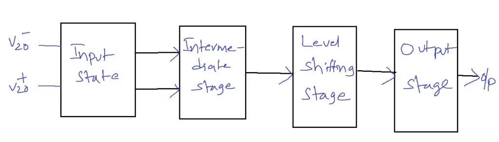
The input state consists of Dual input, balanced output, and differential amplifier.
The intermediate stage consists of dual input and unbalanced output.
The level-shifting stage consists of an emitter follower using a constant current source.
The output stage consists of a complimentary, supply push-pull amplifier.
Differential Amplifier:
Types of Differential Amplifier (DA):
1. Dual input balanced output DA
2. Dual input unbalanced output DA
3. Single input balanced output DA
4. Single input unbalanced output DA
Operational Amplifier Applications:
1. Communications
2. Computers
3. Power and signaling sources
4. Process control
5. Displays and measuring systems
OP-Amp Terminals:
OP-Amp Terminals have five basic terminals, which are
1. Two input terminals
2. One output terminal
3. Two power supply terminals
Linear Integrated Circuits
Classification:
According to the number of components used, linear integrated circuits are classified as:
1. Small Scale Integration (SSI)
2. Medium Scale Integration (MSI)
3. Large Scale Integration (LSI)
4. Very Large Scale Integration (VLSI)
Related FAQs
Q1: What is an operational amplifier (op-amp), and what are its ideal characteristics?
- An operational amplifier (op-amp) is a high-gain voltage amplifier with differential inputs and a single output.
- Ideally, an op-amp has infinite open-loop gain, infinite input impedance, zero output impedance, infinite bandwidth, and zero offset voltage.
- While real op-amps don’t achieve these ideals, they come close enough to be incredibly useful in various circuit designs.
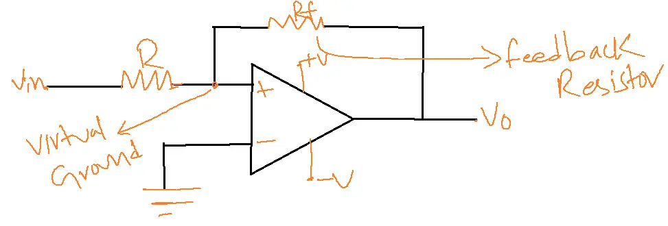
Q2: Explain the concept of virtual short in op-amp circuits, and how it simplifies analysis.
- In an op-amp circuit with negative feedback, the voltage difference between the inverting and non-inverting inputs is virtually zero (ideally zero).
- This “virtual short” concept simplifies analysis by assuming the two input terminals are at the same potential, even though no current flows between them.
- We can quickly determine the relationships between input and output voltages.
- Q3: What are the primary op-amp configurations, and in what scenarios are they typically used?
The most common op-amp configurations include:
- Inverting Amplifier: Produces an output that is the inverted and amplified version of the input. It is used in signal inversion, audio mixers, and analog computers.
- Non-Inverting Amplifier: Produces an output that is the amplified version of the input (same phase). It is used in buffers, voltage followers, and instrumentation amplifiers.
- Summing Amplifier: Adds multiple input signals together. Used in audio mixers and DACs (digital-to-analog converters).
- Integrator: Produces an output that is the integral of the input. It is used in analog computers and signal processing.
- Differentiator: Produces an output that is the derivative of the input. It is used in signal processing and control systems.
Q3: How do feedback resistors affect the gain of an inverting and non-inverting op-amp amplifier?
- An inverting amplifier’s gain is calculated by taking the negative ratio of the feedback resistor (Rf) to the input resistor (Rin), resulting in Gain = -Rf/Rin. In a non-inverting amplifier, the gain is determined by 1 + (Rf/Rin).
- By adjusting the resistor values, we can easily control the amplification factor of the op-amp circuit.
Q4: What are the typical challenges and constraints when utilizing op-amps in practical circuit designs?
Some common issues include:
- Finite Gain: Real op-amps have finite open-loop gain, which can lead to slight deviations from ideal behavior.
- Input Bias Current: Small currents flow into the op-amp inputs, which can cause errors, especially in high-impedance circuits.
- Offset Voltage: Even without any external input, a minor voltage discrepancy may exist between the op-amp’s inputs, potentially causing inaccuracies in the output.
- Bandwidth Limitations: The op-amp’s gain decreases at higher frequencies, limiting its use in high-frequency applications.