
- When a circuit has energy stored elements they don’t allow sudden changes in the transient responses.
- Ex: Inductor for a current and Capacitor to a voltage.
- The inductor acts as an open circuit for a sudden change in current.
- The capacitor acts as a short circuit for a sudden change in voltage.
- Observing the response of a circuit when a system state changes from one state to another is known as a transient response.
- Ex: ON state to OFF state. The circuit is moving from ON to OFF state and vice versa.
- During a transient period, the system response continuously changes. When the circuit has stored elements they charge independently of the source but based on the nature of the circuit elements is known as a natural response.
- The response of a circuit depends on the type of source is known as forced response.
Table of Contents
Transient Response:
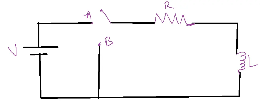
When the switch is moved from portion A at t=0, the current flowing through the circuit increases. Before the instant the switch is closed (at t=0-), the circuit remains open, resulting in zero current through the inductor, iL(0-) = 0.
After the instant switch is closed i.e., at t=0+, the inductor will be open-circuited because it will not allow sudden changes in current.
Therefore at t=0+, iL(0+)=0.
From the above, it can be concluded that iL(0+)= iL(0–)
Procedure to solve transient circuits:
1. Apply KVL to the given circuit after the disturbance. [switch closing or opening]
2. Use the standard solution for the obtained differential equation as follows:
3. Determine the constant c by using initial conditions.
In the case of RL circuits, we can use iL(0+)= iL(0–). Initial current can be taken before the disturbance.
In the case of RC circuits where capacitor performance is based on voltage phenomenon the above rule will not be valid, so initial conditions [current] can be taken at the time of disturbance. Because during disturbance capacitance will be short-circuited.
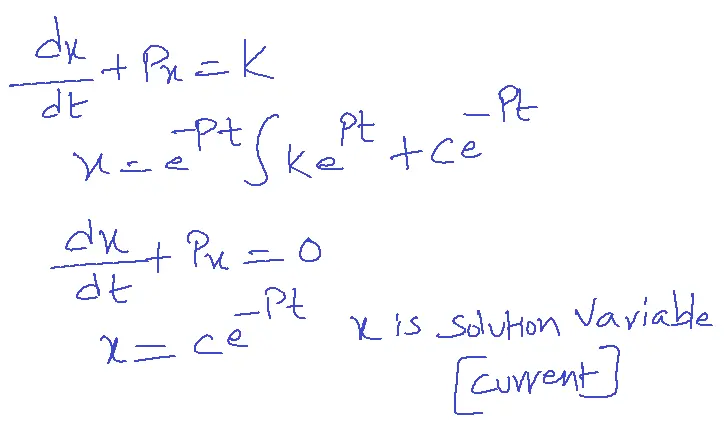
For differential equation di/dt + Pi = K, solution will be i=e-Pt integral K(ePt )+ ce-Pt
For differential equation di/dt + Pi=0, solution will be i= ce-Pt
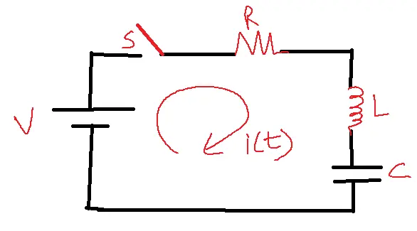
Series RL Circuit with DC Excitation:
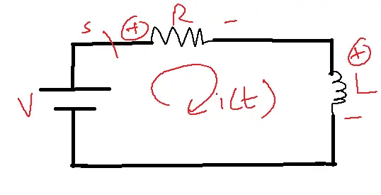
V=iR+L(di/dt) [Applying KVL]
V/L= i(R/L)+di/dt
di/dt+(R/L)I = V/L →1
dx/dt+Px=K →2
By applying KVL to the given circuit
V=iR+L(di/dt)
Arranging the given equation in differential equation form
di/dt +(R/L)i=V/L
From the standard form of Non-homogenous differential equation
dx/dt+Px=K
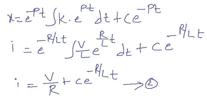
solution for the above equation can be written as
t=0, i=0
0=V/R+C.
C=-(V/R)
Substitute the C value in 2 equations, then
i=V/R(1-e(-R/L)t) →3
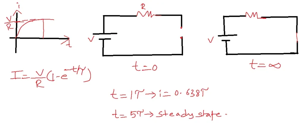
From 3, at t=0, i=0
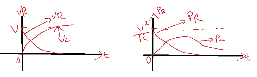
The system reaches to steady state approximately. In steady-state, the inductor effectively acts as a short circuit, allowing the current to reach its maximum value of i=V/R, as depicted in the figure. The current transitions from its initial state to this steady-state value exponentially, following equation 3.
Rate of Rise of current given by the time constant
Tov(T)=L/R
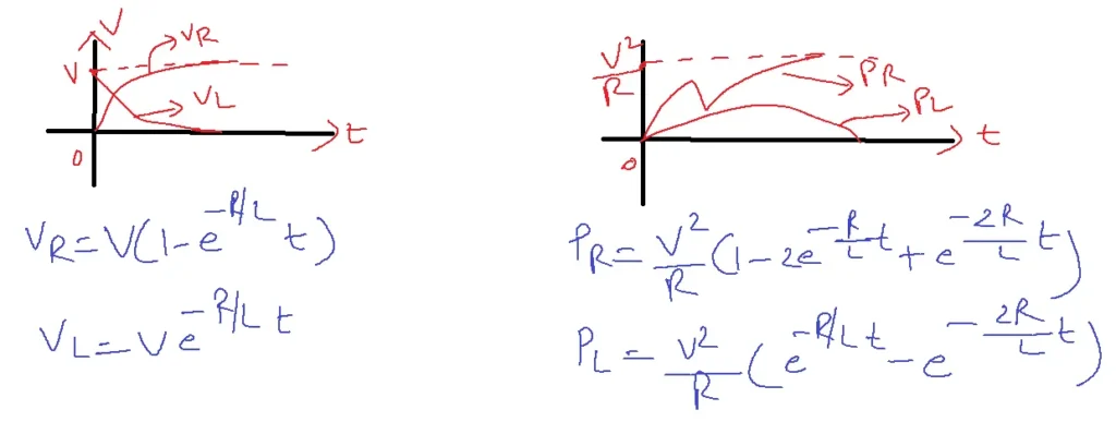
The voltage across Resistance VR=iR and Power across Resistance are given in the below figure.
Series RC Circuit for DC Excitation:
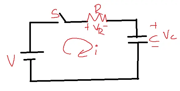
The same procedure is followed in the Series RL circuit with DC Excitation
t=0, the switch is closed.
Apply KVL
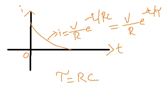
C=V/R
i=V/R e-t/RC
at t=infinity, i=0 [capacitor is open-circuited]
The voltage across resistance VR=V.e-t/RC
The voltage across resistance VC=V.e-t/RC+K
At t=0, VC=0
Therefore C is short-circuited.
K=V
Power Flow in the Resistance
PR=V2/R(e-2t/RC)
Power Flow in the Capacitance
PC=V2/R(e-t/RC)(1- e-t/RC)
Series RLC Circuit by DC excitation:
Series RLC Circuit is excited by DC excitation through a switch, that is closed at t=0.
Then by applying KVL to the given circuit after t=0+
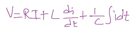
Differentiating concerning t, we get
0= R di/dt+Ldi2/dt2+i/c
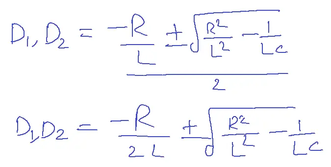
d2i/dt2+R/L(di/dt)+i/LC=0
(D2+R/L(D)+1/LC)i=0 [Auxilliary equation]
D=d/dt
The given system has two energy-stored elements which represent the second-order system. These two elements exchange their energies which produces an oscillatory response.
The response is a function of the frequency of oscillations and damping force.
We can represent this response by a second-order equation as a function of…
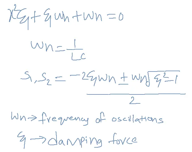
The roots of the given second-order equation can be given as
Wn=1/LC
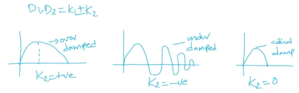
D1,D2=K1±K2
Problem: Write the current equation for a given circuit when the switch is closed at t=0
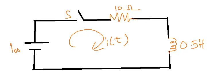
Sol:
When a disturbance is created, apply KVL to the circuit
100=10I+0.5(di/dt)
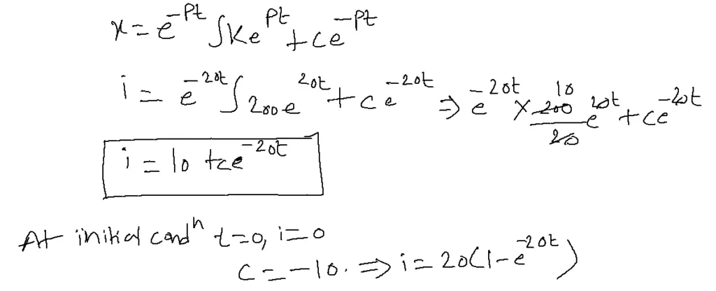
dI/dt+20I=200—1
standard equation
dI/dt+Px=K
P=20, K=200
Related FAQs
Q1: What is a transient response in electrical circuits, and why is it important to analyze?
- A transient response is the temporary behavior of a circuit immediately after a sudden change, such as switching on or off a power source or changing a component value.
- Transient analysis is essential as it unveils a circuit’s dynamic behavior under changing conditions, empowering engineers to design robust, dependable systems that withstand voltage or current spikes.
Q2: How do we differentiate between natural and forced responses in transient analysis?
- The natural response is the circuit’s behavior due to stored energy (e.g., in capacitors or inductors) after the source is removed or changed.
- It decays over time and depends on the circuit’s inherent properties.
- The forced response is the circuit’s behavior due to the applied input (source).
- It continues as long as the input is present and mirrors the input’s form (e.g., sinusoidal, step, etc.).
Q3: What are the common methods used for solving transient problems in network analysis?
Several methods are employed, including:
- Classical Differential Equation Approach: Directly solving the circuit’s differential equations.
- Laplace Transform Method: Simplifying differential equations into algebraic equations, solving in the Laplace domain, and then converting back to the time domain.
- Numerical Methods: Using computer simulations and algorithms to approximate the transient response when analytical solutions are complex.
Q4: How does the time constant affect the transient response of an RC or RL circuit?
- The time constant (τ) determines how quickly a circuit’s transient response decays or rises.
- In RC circuits, τ = RC, while in RL circuits, τ = L/R. A larger time constant means a slower response, while a smaller time constant means a faster response.
- Generally, after 5 time constants, the transient is considered to have settled.
Q5: What are some practical applications of transient analysis in electronics and communication engineering?
Transient analysis is essential in:
- Power Electronics: Designing switching circuits, assessing overvoltage and overcurrent protection.
- Communication Systems: Analyzing signal integrity, minimizing distortion and ringing.
- Control Systems: Studying the response of systems to sudden disturbances or changes in setpoints.
- Digital Electronics: Analyzing timing delays and signal propagation in high-speed circuits.