
A transformer is a static device that transforms electrical energy from one circuit to another with different energy levels at constant frequency. It operates based on the principle of mutual induction.
Table of Contents
Two windings wound on silicon steel as shown in the figure.
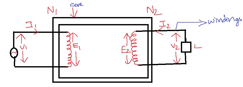
- N1 → primary coil turns
- N2 → secondary coil turns
- V1 → primary applied voltage
- V2 → secondary applied voltage
- E1 → primary induced emf
- E2 → secondary induced emf
According to Faraday’s law
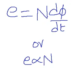
Therefore, the number of turns induced emf in windings varies. If N1> N2 then V1>V2. This is a step-down transformer. If N1<N2, then V1<V2 then it is step up transformer. If N1=N2, then V1=V2 it is one-one transformer.
Therefore E1/E2= N1/N2 and V1/V2 = N1/N2
Equivalent circuit of primary coil:
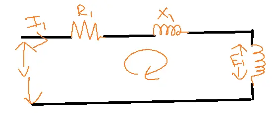
R1X1=Z1 primary winding
By KVL, V1=I1Z1 + E1
I1Z1 is the primary drop if it is negligible then V1=E1.
Therefore V1/V2 = N1/N2.
Construction:

Main parts of Transformer:
1. Main Tank – protects transformer.
2. Core – The core, composed of highly stable silicon steel, facilitates the passage of an increased magnetic flux.
3. Windings – they are made of Cu material.
4. Brushings – to collect winding terminals outside of the tank.
5. Oil conservator – Oil conservators, used in high-power transformers, efficiently dissipate heat through oil cooling, offering faster temperature reduction than air or water cooling methods.
EMF equation of a Transformer:
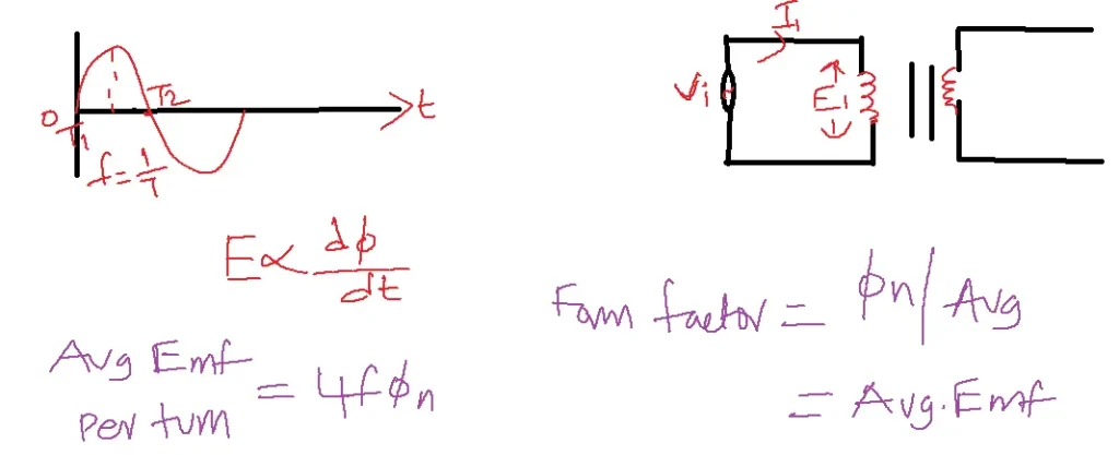
For no load E1 = V1, E2 = V2
V2/V1 = N2/N1.
Types of transformers:
1. Based on construction
2. Based on cooling methods.
Based on construction:
1. Core type transformer
2. Shell type transformer
| Core Type | Shell Type |
| Core surrounds winding | Winding surrounds core |
| More amount of Cu is required | Less amount of Cu is required |
| Losses are high | Losses are low |
| Flux linkages with the secondary coil are low | The high amount of flux links with the secondary coil |
| Safest construction | Complex construction |
| Electric isolation is high | Electric isolation is low |
Based on cooling methods used:
1. Oil-filled self-cooled – used for moderate power ratings. This method takes less time to cool it.
2. Oil filled Oil Cooled – used for high power ratings. This method takes much less time than all methods.
3. Air blast oil cooled – used for low power ratings. This method takes a long time to cool the transformers.
Based on applications: Transformers are of three types:
1. Power – high power, used for power transmissions.
2. Distributive – medium power, used for power distribution.
3. Instrument – measure high voltage and current levels in electrical systems.
Phasor Diagram of Transformer on no-load:
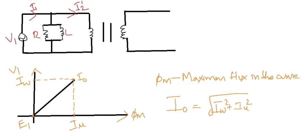
- I1 → primary current
- I0 →no load component in the primary current
- I2’ → load component in primary current
- Iw→ working component
- IU → magnetizing component, where the flux is produced.
- E1 and E2 vectors will be in phase opposition with V1 to satisfy lens law.
- E1 and E2 are the results, while V1 is the cause.
Losses of a Transformer:
losses are copper losses and core losses.
Core losses are hysteresis losses and eddy current losses.
Efficiency:
Input = output + losses
n = output/input x 100
n = output/output + losses x 100
wi=wCu
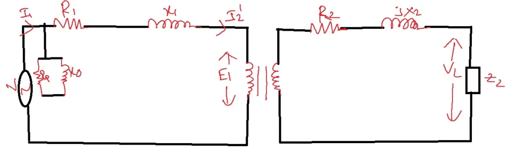
Regulation and Equivalent circuit:
I0 – load current
% Regulation = ( (V2 – V20 )/V2 )x 100
V20 – no load secondary voltage
Voltage regulation is defined as a change in voltage from no load to full load
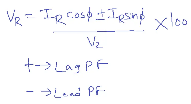
VR = (V20 – V2 )/V2 )x 100
V2 – full load voltage
VR is also affected by the power factor. So voltage regulation in terms of power factor can be written as
V2/V1 = N2/N1 = I1/I2.
Applications
- Power generation, transmission, distribution, lighting, audio systems, and electronic devices are a few uses.
- Power generation: Power plants utilize them to boost the voltage of the electricity produced by the power plants before sending it to the grid.
- It is used in the transmission and distribution of electricity to modify the voltage of the energy as it travels from power plants to residences and commercial buildings.
- Lighting: Before power is transmitted to lightbulbs, it is employed in lighting systems to lower the voltage of the electricity.
- Audio systems: It is employed in audio systems to modify the electrical power before it reaches the speakers.
- Electronic devices: Computers, TVs, radios, and cell phones are just a few gadgets that employ it.
- It is an essential component of the electrical grid and is employed in different ways to guarantee the effective and safe delivery of electricity.
Related FAQs
Q1: What is the basic operating principle of a transformer, and why is it essential in electrical power systems?
- It operates on the principle of electromagnetic induction.
- It transfers electrical energy from one circuit to another through mutual inductance between two or more coils (windings).
- It is crucial in power systems because they allow for efficient voltage transformation, stepping up voltage for long-distance transmission and stepping down for safe distribution to consumers.
Q2: Explain the difference between step-up and step-down transformers, and how their turn ratios relate to voltage transformation.
- Step-up increases voltage (lower current) and has more turns in the secondary winding than the primary.
- Step-down decreases the voltage (higher current) and has fewer turns in the secondary winding.
- The turns ratio (N2/N1) directly determines the voltage transformation ratio (V2/V1), where N is the number of turns and V is the voltage.
Q3: What is the equivalent circuit model of a transformer, and how is it used in network analysis?
- The equivalent circuit model is ideal with resistances and reactances representing core losses, winding losses, and leakage flux.
- It allows for analyzing transformer performance under different load conditions and calculating parameters like efficiency, voltage regulation, and power factor.
Q4: How does transformer efficiency vary with load, and what factors contribute to losses in a transformer?
- Its efficiency generally increases with load up to a certain point, then starts to decrease.
- Losses include copper losses (I²R losses in windings), core losses (hysteresis and eddy current losses), and stray losses.
- Minimizing these losses through design and material selection is crucial for maximizing efficiency.
Q5: What are some common applications of transformers in electronics and communication systems?
Besides power transmission and distribution, these are used for:
- Impedance matching: Optimizing power transfer between circuits with different impedances.
- Isolation: Providing electrical separation between circuits for safety and signal integrity.
- Voltage regulation: Maintaining a stable output voltage under varying load conditions.
- Power supplies: Stepping down the AC mains voltage and converting it to DC for electronic devices.