
Self Inductance and Mutual inductance are key concepts in Faraday’s law of electromagnetic induction.
Self Inductance:
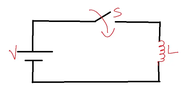
If the current flow through the coil is varied either by switching or by varying magnitude with a particular arrangement then the flux linkage with the other portion of a coil varies. According to Faraday’s law, this change in flux linkage induces an emf in the coil.
The ‘–‘ sign indicates lens law.
This emf opposes changes in the current.
So the property of current is said to be which opposes changes in current.
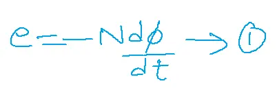
It is complicated to calculate the emf from a single flux.
So e = -Ldi/dt →2 can be used instead of 1.
Therefore from 1 and 2
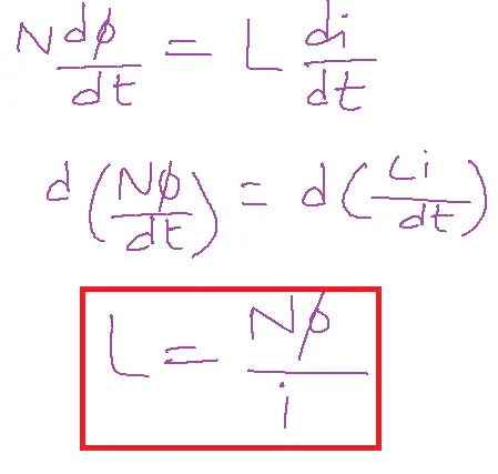
Units of Inductance are Veber Turns/Amp or Henry.
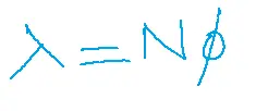
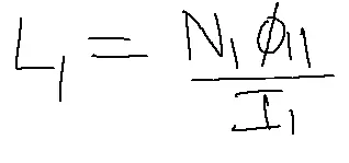
Inductance can be defined as the ratio of flux linkage to current flowing through the coil. Similarly, Self Inductance can be defined as emf producing due to flux linking with its coil terms. Later I1 is currently flowing through the coil phi11 flux produced by the coil N1 number of turns of a coil then Self Inductance.
Mutual Inductance:
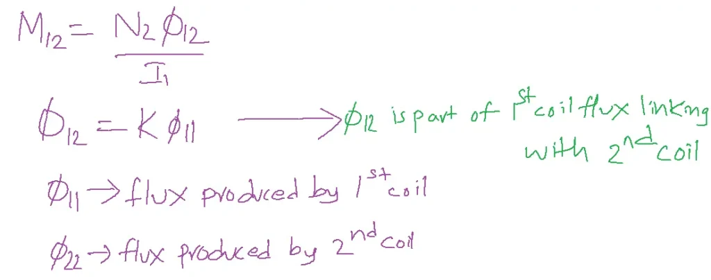
Emf is induced in a coil due to flux linking from the other coil or neighbor coil flux linking with the own coil terms, i.e.,
Allow I1 current to pass through the first coil, with N1 turns when two circuits are brought close. N2 rotates and I2 current flows through the second coil.
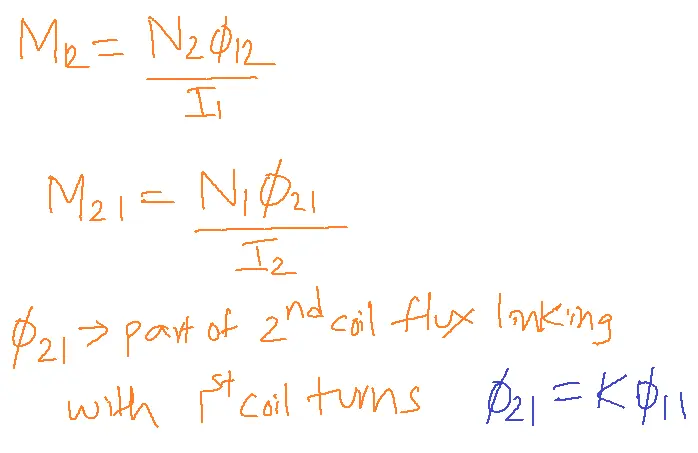
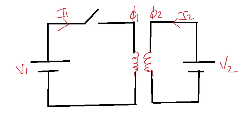
Table of Contents
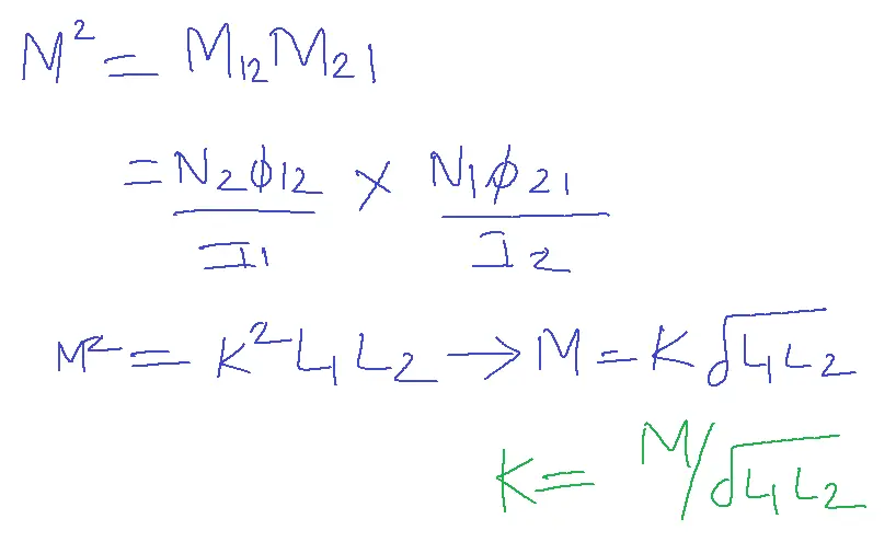
Coefficient of coupling (K):
The coefficient of coupling is the percentage or a fraction of flux linking with the neighbor coil, to create an emf.
The coefficient of coupling K ranges from 0 to 1. i.e., 0≤K≤1.
From the relation between M and L1, L2
as K lies between 0≤K≤1.
Let phi 12 be a part of the first coil flux linking with second coil terms
Self Inductance can be written for each coil
Assuming linear magnetic medium, M12=M21 implies M2 = M12.M21
Inductance can also be derived by definition
From a relation between B and H B=µH where µ=µo µr
µo = absolute permeability = 4π x 10-7 H/m
µr = relative permeability depends on the core material
For an air core µr =1
According to an Ampere circuital law H=nI/L
Substituting these terms instead of in the above expression
L=NBA/I
=N µo µrNIA/lI
L = N2µo µrA/l
A – area of the coil
l-length of the coil.
M12 = N22 µo µrA1 /l1
M21 = N12 µo µrA2 /l2
A – area of cross-section of a core
l – length of the coil
n – number of turns
Example:
1. Two coils have a mutual inductance of 3.25 x 10⁻⁴H. The current in the first coil increases at a uniform rate of 830 A/sec. What is the magnitude of induced emf in the second coil? Suppose the current is instead in the second coil, what is the magnitude of induced emf in the first coil? Will they equal or not?
Solution:
M=3.25 x 10⁻⁴H
diV/dt= 830 A/sec
E1= -Mdi2/dt = -3.25 x 10-4 X 830 = -259.7 x 10⁻³ V.
E2 = -Mdi1/dt = -3.25 x 10-4 X 830 = -259.7 x 10⁻³ V.
2. Given two coupled inductors L1 and L2 then mutual induction satisfies
Solution:
0≤K≤1
M≥0
The relation between M and L→M is less than or equal to the square root of L1, L2
Dot Convention:
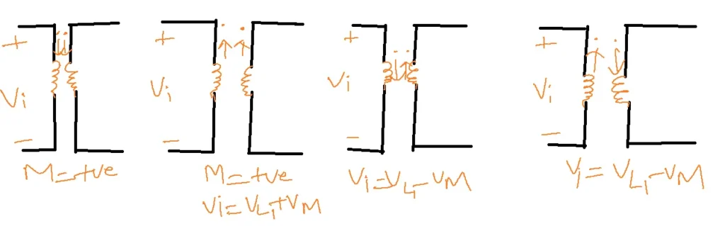
- To identify the polarities of mutually induced EMFs and mutual inductance direction.
- The dot convention rules have been proposed. It states that
- If both the coil dots specify entry or leaving current directions then the mutual inductance and an emf induced in the neighbor coil are positive.
- If one coil dot specifies current entering and another or neighbor coil dot specifies leaving current direction or vice versa the mutual inductance will be negative, and emf induced also negative.
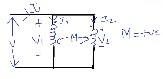
Write voltage equations for two coils based on mutual inductance using the dot convention rule.
V1=VL+VM
V1=L1di1/dt + M di2/dt
V2= L2di2/dt + M di1/dt
Above V1 and V2 equation obtains when M is positive[both dots are entering or leaving the ciircuit]
V1= VL1-VM = L1di1/dt –Mdi2/dt
V2 = VL2 – VM = L2di2/dt – Mdi1/dt
Above V1 and V2 equation obtains when M is negative[one dot is entering and other dot is leaving the ciircuit]
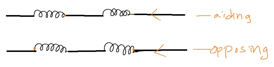
Series aiding:
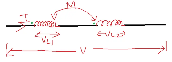
V = VL1+VL2
Leq=L1+L2+2M
V = Leqdi/dt
Series opposing:
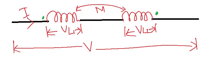
Leq=L1+L2-2M
V = Leqdi/dt
Electrical equivalent circuits for series aiding and opposing:
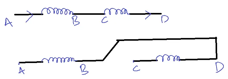
Note: Dots on the coil sides represent the current’s entry point, and since the sides are in series, the dots collectively indicate the direction of the current entering or leaving the coil as a whole. It is said to be series aiding.
Leq=L1+L2+2M
When the dot is located at the entering side of one coil and the leaving side of another coil it is said to be series opposing when they are in series connection.
Leq=L1+L2-2M
Alternate connections for series aiding and opposing:
Parallel Aiding:
M = positive
i = I1+I2
V1 = L1 di1/dt + M di2/dt
V2 = L2 di2/dt + M di1/dt
V1 = V2 [parallel connection]
Leq = L1L2-M2/L1+L2-2M
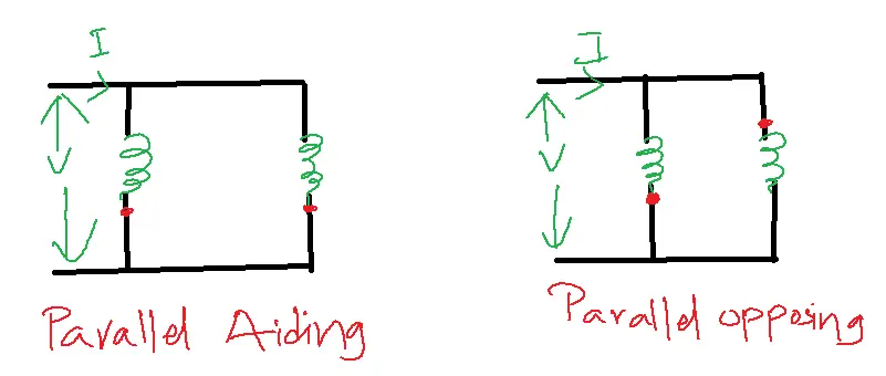
Similarly for parallel opposing
Leq = L1L2-M2/L1+L2+2M
Related FAQs
Q1: What is the fundamental difference between self-inductance and mutual inductance in circuit analysis?
- Self-inductance is the property of a coil to oppose any change in the current flowing through itself.
- It’s analogous to inertia in mechanics.
- In contrast, mutual inductance refers to the phenomenon where a current change in one coil generates a voltage in a separate, nearby coil.
- It’s the principle behind transformers.
Q2: How does self-inductance affect the transient response of an RL circuit (resistor-inductor)?
- In an RL circuit, self-inductance causes the current to lag behind the voltage.
- When the circuit is switched on or off, the inductor resists the sudden change in current, leading to a gradual rise or fall in current over time.
- The transient response is characterized by a time constant determined by the inductance and resistance values.
Q3: What is the significance of the dot convention in analyzing circuits with mutual inductance?
- The dot convention is crucial in determining the relative polarities of induced voltages in mutually coupled coils.
- When the current enters the dotted terminal of one coil, the induced voltage in the other coil has a positive reference at its dotted terminal.
- This helps in accurately developing equations for circuit analysis, especially in transformers and coupled inductor circuits.
Q4: How can we calculate the overall inductance of inductors connected in series or parallel when mutual inductance is present?
- Series (Aiding): L_eq = L1 + L2 + 2M (M is the mutual inductance)
- Series (Opposing): L_eq = L1 + L2 – 2M
- Parallel: The calculation is more complex and depends on the dot convention and whether the mutual inductance aids or opposes the self-inductance. It’s often easier to analyze using mesh or nodal analysis.
Q5: What are some practical applications of mutual inductance in electronics and communication engineering?
- Mutual inductance is the backbone of transformers, used for voltage level conversion in power systems and impedance matching in RF circuits.
- It’s also used in inductive coupling for wireless power transfer and communication, as well as in metal detectors and proximity sensors.