
S Parameters, or Scattering Parameters, are a crucial concept in microwave engineering, used to describe the electrical behavior of linear microwave networks. These parameters help engineers design, analyze, and optimize microwave circuits, ensuring reliable and efficient performance.
What are S Parameters?
S Parameters are complex numbers that describe the relationship between incident and reflected waves in a microwave network. They fully characterize a network’s electrical properties, including gain, loss, and reflection.
Key S Parameters:
1. S11 (Return Loss): Measures the amount of signal reflected to the source.
2. S21 (Insertion Loss): Measures the amount of signal transmitted through the network.
3. S12 (Reverse Isolation): Measures the amount of signal reflected to the load.
4. S22 (Output Return Loss): Measures the amount of signal reflected to the load.
Table of Contents
Importance of S Parameters:
1. Network Analysis: S Parameters help engineers analyze and optimize microwave networks.
2. Circuit Design: S Parameters enable the design of reliable and efficient microwave circuits.
3. Troubleshooting: S Parameters aid in identifying and resolving issues in microwave networks.
As we just stated, when power is applied at one port on a two-port network, as seen in the following image, most of the power escapes from the second port and part of it reflects to the same port. In the following figure, current flows I1 or I2 depending on whether V1 or V2 is applied.
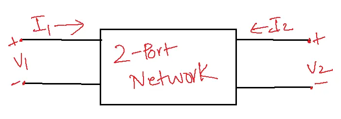
Applying the source to the opposite port introduces two further combinations that warrant consideration. Therefore, 2 × 2 = 4 combinations are expected for a two-port network.
The S-parameters, also known as the Scattering Parameters, are a matrix form referred to as the “Scattering Matrix” and are used to define the traveling waves and their corresponding powers when they scatter out through the ports and the Microwave junction.
Scattering Matrix:
All conceivable power transfer scenarios between the multiple input and output ports within a microwave junction are encapsulated within this square matrix. “Scattering SS Parameters” or “Scattering Coefficients” are the names of the components in this matrix.
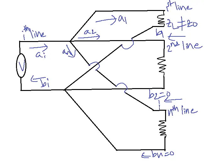
In this instance, the incident wave (a1) and the reflected wave (b1) are connected by the ith line to the source.
If b1 and a1 have the following relationship: b1=(reflection coefficient)a1=S1ia1
Where S1i = Reflection coefficient of 1st line
1 = Reflection from 1st line
i = Source linked at ith line.
The power is transmitted to the load if the impedance matches. Very unlikely, that the characteristic impedance and the load impedance don’t match. The reflection then takes place. In other words, reflection happens if Zl≠Zo.
On the other hand, if this mismatch exists for multiple ports, say ′n′ ports, then i=1 to n
Therefore, we have b1=S11a1+S12a2+S13a3+……………+S1nan b2=S21a1+S22a2+S23a3+……………+S2nan
bn=Sn1a1+Sn2a2+Sn3a3+……………+Snnan
If everything is maintained in matrix form,
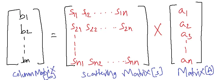
[b]=[S][a]
Properties of S-Matrix:
- The scattering matrix is indicated as [S] Matrix.
- [S] is always a square matrix of order n x n.
- [S]n x n
- [S] is a symmetric matrix.
- Sij=Sji
- [S] is a unitary matrix [S][S]*=I
- When similar terms from any other row or column are multiplied by their complex conjugate, the products of all terms in that row or column add up to zero.
- SikSik*=0
- For k≠j
- k=1, 2, 3, …… n
- j=1, 2, 3, …… n
Advantages of S Parameters:
1. Accurate Network Analysis: parameters provide microwave networks with a precise characterization making analysis and optimization possible.
2. Efficient Circuit Design: S Parameters facilitate the design of reliable and efficient microwave circuits, reducing design time and errors.
3. Easy Troubleshooting: S Parameters aid in identifying and resolving issues in microwave networks, simplifying troubleshooting.
4. Flexible Measurement: S Parameters can be measured using various techniques, including vector network analysis.
5. Scalability: S Parameters apply to frequencies, from RF to millimeter waves.
Disadvantages of S Parameters:
1. Complexity: S Parameters can be difficult to understand and interpret, requiring expertise in microwave engineering.
2. Measurement Challenges: Accurate measurement of S Parameters requires specialized equipment and techniques.
3. Limited Dynamic Range: S Parameters may not accurately represent networks with very high or low reflection coefficients.
4. Frequency Dependence: S Parameters are frequency-dependent, requiring measurements at multiple frequencies.
Applications of S-Parameters:
- Characterizing Microwave Components: S-parameters are essential for describing the behavior of microwave components like amplifiers, filters, and antennas. They provide information on gain, loss, reflection, and transmission characteristics, helping engineers select the right design components.
- Designing Microwave Circuits and Systems: S-parameters are used to analyze and design complex microwave circuits and systems. They allow engineers to simulate and optimize the performance of their designs before building physical prototypes, saving time and resources.
- Impedance Matching and Network Analysis: S-parameters are invaluable for impedance matching, ensuring maximum power transfer between components in a microwave system. They also facilitate network analysis, enabling engineers to troubleshoot and optimize the performance of existing systems.
- Signal Integrity Analysis: S-parameters play a crucial role in high-speed digital systems by evaluating signal integrity and pinpointing potential problems such as reflections and crosstalk. This is crucial for ensuring reliable data transmission and preventing signal degradation.
- Antenna Design and Measurement: S-parameters are essential in antenna design and measurement, characterizing key performance aspects like gain, radiation pattern, and impedance, empowering engineers to optimize antennas for specific uses.
FAQs of S-Parameters
1. What are S-parameters?
- S-parameters, or scattering parameters, quantify how microwave signals interact with a network or device, specifically in reflection and transmission, and are represented by complex numbers.
- They provide a comprehensive way to characterize the behavior of microwave components and systems.
2. Why are S-parameters used in microwave engineering?
- S-parameters are widely used in microwave engineering due to their several advantages:
- Frequency-dependent: They accurately represent the behavior of components across a range of frequencies.
- Easy to measure: This can be measured directly using a network analyzer.
- Convenient for analysis and design: Employ software tools to expedite and improve the accuracy of circuit simulation and optimization.
- Suitable for complex networks: Can handle multiple ports and interconnected components.
3. What do the individual S-parameters represent?
- S11: Input reflection coefficient, representing the portion of the incident wave reflected from the input port.
- S21: Forward transmission coefficient, representing the portion of the incident wave transmitted from the input port to the output port.
- S12: Reverse transmission coefficient, representing the portion of the incident wave transmitted from the output port to the input port.
- S22: Output reflection coefficient, representing the portion of the incident wave reflected from the output port.
4. How are S-parameters measured?
- S-parameters are typically measured using a Vector Network Analyzer (VNA). The VNA sends a known signal into the device under test (DUT) and measures the reflected and transmitted signals at each port.
5. What are the applications of S-parameters in microwave engineering?
- Component characterization: Determining gain, loss, reflection, and transmission characteristics of microwave components.
- Circuit and system design: Analyzing and optimizing the performance of microwave circuits and systems.
- Impedance matching: Ensuring maximum power transfer between components.
- Signal integrity analysis: Identifying potential issues in high-speed digital systems.
- Antenna design and measurement: Characterizing antenna performance parameters.