
An electrical circuit that consists of a resistor (R) and an inductor (L) connected in combination is known as an RL circuit. The circuit is used to control the flow of electrical current
How Does an RL Circuit Work?
In this circuit, the resistor opposes the current direction, while the inductor stores energy in a magnetic field. When a voltage is applied to the circuit, the current flows through the resistor and inductor, causing the inductor to charge. As the inductor charges, it generates a back electromotive force (EMF) that opposes the change in current.
Characteristics of RL Circuits
- Time constant (τ): The time it takes for the current to reach 63.2% of its maximum value.
- Frequency response: RL circuits are used to filter out specific frequencies.
- Damping: The circuit’s ability to reduce oscillations.
Types of RL Circuits
- Series RL circuit: The resistor and inductor are connected in series.
- Parallel RL circuit: The resistor and inductor are connected in parallel.
Table of Contents
The behavior of RC low pass and high pass circuits for various types of input waveforms are discussed in RC circuits, suppose the capacitor C and resistor R are replaced by resistor R’ and inductor L’ respectively then if time constant RC = L/R’. The result of the output is changed.
When a large time constant is required, the value of the inductor is high, this inductor is rarely used and made by iron core conductors which are very expansive compared to the capacitor and large because of this non-linear property [iron core distorts output] it is undesirable, for this application we choose RC circuit.
Low-time constant applications can benefit from a small, low-cost air core inductor.
Properties of Inductor
- The inductor does not allow sudden changes in current.
- The voltage across inductor L is given by
V = L di/dt = 1/L integral of V dt.
3. For constant current di/dt = 0, V=0 then it acts as a short circuit.
4. For sudden changes in current di/dt=infinity, V=infinity, it acts as an open circuit.
5. Therefore, current through an inductor cannot change instantaneously.
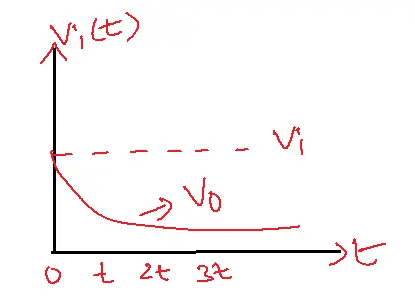
High pass RL circuit
For low frequencies, reactance XL=WL or 2πfL. The reactance offered by the inductor is very low and acts as a short circuit, the output is zero.
For high frequencies, the reactance offered by the inductor is very high and acts as an open circuit the output is equal to the input. Thus it allows the high frequency signals and opposes the low frequency signals. Therefore it acts as a high-pass circuit.
Step Input Response of High Pass RL Circuit
Vo(S)=Vi(S).SL/SR+SL
=V/S. SL/L(S+R/L)
=V/ S+R/L)
Apply Inverse Laplace Transform’
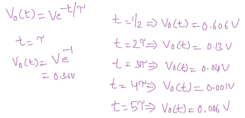
Vo(t)=Ve-(R/L).t
High pass RL circuits for step inputs output voltage is
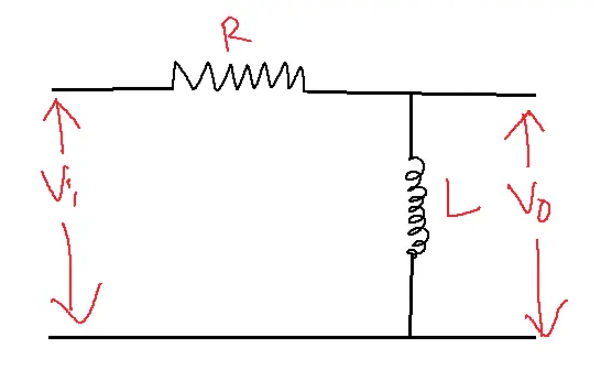
Low Pass RL Circuit
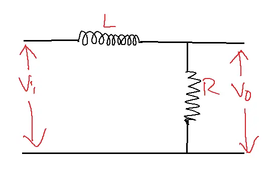
For low-frequency signals, the reactance offered by the inductor is very low and acts as a short circuit then the total input appears across the resistor output equals the input.
For high frequencies, the reactance offered by the inductor is high and acts as an open circuit then the total input that appears across the inductor output is zero thus it allows low-frequency signals and rejects all high-frequency signals. Therefore it acts as a low-pass RL circuit.
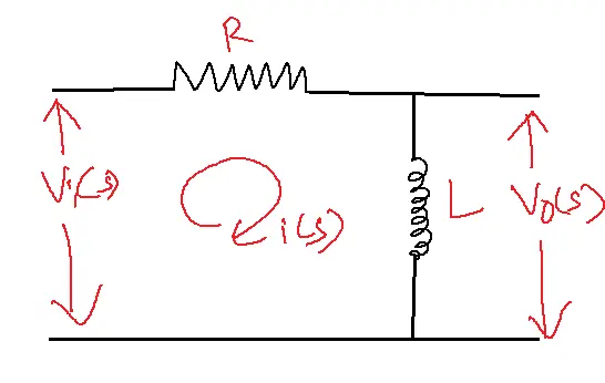
Step Input Response of Low Pass RL Circuit
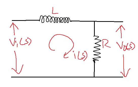
Vi(t)=V
Vi(S)=V/S
Vo(S)=Vi(S).R/R+LS
=V/S. R/R+LS
= V/S.R/L(1+R/L)
=VR/L . 1/S(1+R/L)
A=L/R, B=-L/R
VR/L[(L/R)/S + (-L/R)/S+(R/L)]
=V[1/S – 1/S+(R/L)]
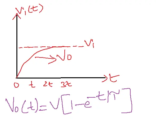
Apply Inverse Laplace Transform
Vo(t)=V[1-e-(R/L).t]
The step response of low pass RL circuit output voltage is
Note: The sudden changes in the DC are called a step when it is switched ON.
Advantages of RL Circuit
1. Simple and Cost-Effective: These circuits are simple to design and implement, making them a cost-effective solution.
2. Effective Filtering: These circuits filter out unwanted frequencies, making them useful in audio equipment and power supplies.
3. Oscillator Applications: These circuits create oscillators essential in various applications.
4. Current Limiting: These circuits can limit current, protecting devices from damage.
5. Energy Storage: The inductor in this circuit can store energy, making it useful in power supplies and other applications.
Disadvantages of RL Circuit
1. Limited Frequency Range: These circuits have a limited frequency range, making them less versatile than other circuits.
2. Inductor Saturation: The inductor in this circuit can saturate, reducing its effectiveness.
3. Resistor Power Dissipation: The resistor in this circuit can dissipate power, leading to energy loss.
4. Slow Response Time: These circuits can have a slow response time, making them less suitable for high-speed applications.
5. Sensitive to Component Values: These circuits are sensitive to component values, requiring precise component selection.
Applications
- Timing Circuits and Pulse Generation: These circuits in digital circuits create predictable time delays and signal shaping due to the inductor’s energy storage and release properties.
- Filtering and Noise Reduction: These circuits in digital systems act as low-pass or high-pass filters crucial for noise reduction and signal conditioning in digital communication and processing.
- Pulse Transformers and Coupling: These circuits with transformers couple and isolate pulses in digital circuits, maintaining electrical isolation and preventing signal interference.
- Switch Debouncing: These circuits eliminate unwanted multiple transitions from mechanical switches, ensuring clean digital signals.
- Power Supply Filtering and Smoothing: These circuits in digital power supplies filter out high-frequency noise and ripple, ensuring a stable and clean power supply for digital circuits, enhancing their performance and reliability.
FAQs
1. What is an RL circuit?
- An RL (Resistor-Inductor circuit) is a fundamental electrical circuit consisting of a resistor (R) and an inductor (L) connected in series or parallel.
- It’s crucial for understanding the behavior of circuits with both resistance and inductance.
2. How does an inductor behave in an RL circuit?
- An inductor opposes changes in current flow due to its inherent property of inductance. In this circuit, the inductor initially resists the flow of current when a voltage is applied, but eventually allows current to flow steadily once the magnetic field is established.
3. What is the time constant of an RL circuit?
- This circuit’s time constant (τ) represents the duration for its current to reach about 63.2% of its final steady-state value after a voltage change.
- It is calculated as τ = L/R, where L is the inductance and R is the resistance.
4. How are RL circuits used in pulse and digital circuits?
- These circuits have various applications in pulse and digital circuits, including:
- Timing circuits: The time constant of this circuit can be used to create delays and timing intervals in digital systems.
- Pulse shaping: These circuits can modify the shape of pulses, filtering out high-frequency noise and improving signal integrity.
- Power supplies: These circuits filter and smooth power supply outputs by inductors.
- Relay circuits: These circuits control the timing and behavior of relays in switching applications.
5. What are the key differences between RL and RC circuits?
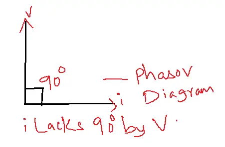
- RL circuits: Store energy in a magnetic field (inductor), current lags voltage.
- RC circuits: Store energy in an electric field (capacitor), current leads voltage.
- Time constant: The time constant is L/R, while RC time constant is RC.