
The preferred communication method within the public switched telephone network is Pulse Code Modulation, developed by Alex H. Reeves in 1937. With PCM, digital voice and data can be easily combined into a single, high-speed digital signal propagated over metallic or optical fiber cables. The pulses in pulse code modulation have a set amplitude and length. In a binary system like PCM, a pulse or absence of a pulse within a designated time window denotes a logic 1 or logic 0 state.
Table of Contents
Block Diagram of Pulse Code Modulation:
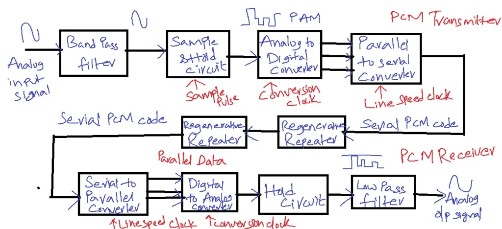
The Transmitter section receives a continuous message signal, which is then processed through a low-pass filter.
Discrete value is output obtained from the encoder.
In the Transmission path, a regenerated PCM wave is generated which is given as input to the regenerative circuit in the receiver section.
To be sent, the analog signal is first sampled and then transformed into a serial n-bit binary code. Every code has the same amount of bits and needs the same amount of transmission time. Digital audio is used in CDs and computers, among other applications.
The public switched telephone network (PSTN) primarily relies on Pulse Code Modulation (PCM), a technique invented by Alex H. Reeves in 1937, to efficiently combine voice and digital data into a single, high-speed digital signal for transmission over optical or metallic fibers. PCM pulses are defined by their amplitude and length. A pulse or lack of pulse within a predetermined timeslot indicates either a logic 1 or 0 condition in the PC Misabinary System.
A simplified block diagram of a single-channel, dual-channel PCM system is depicted in the above figure. The bandpass filter restricts the analog input signal’s frequency to the 300–3000 Hz standard voice band frequency range. The circuit that samples and holds the analog input signal regularly transforms those samples into numerous PAM signals. The PAM samples are converted by the analog-to-digital converter (ADC) into parallel PCM codes. The codes are processed by a parallel-to-serial converter, which then sends them as a stream of digital pulses over the transmission line in a sequential binary format. Repeaters are placed at specific intervals to regenerate the digital pulses and maintain signal integrity.
Serial pulses from the transmission line are converted to parallel PCM codes at the receiver side by a serial-to-parallel converter. Parallel PCM codes are converted to multilevel PMM signals by the digital-to-analog converter (DAC). The hold circuit restores the PAM signals to their original analog form by acting as a low-pass filter. A codec is an integrated circuit that carries out the PCM encoding and decoding operations (coder/decoder).
Bandwidth of Pulse Code Modulation:
fm-maximum message frequency
fc=2fm fm=fs/2
BW≥fm
BW≥fs/2
BW≥Rb/2
Fc-sampled frequency
Rb-bit rate
Let, fm=WHz
fs=2W
L number of levels are present in Q-wave.
2n≥L or 2n =L then n=log2L
The bit rate of the number of bits per second X number of samples per second is Rb
Rb=2NW
Rb=2NW
BW≥NW
BW≥1/2 nfs.
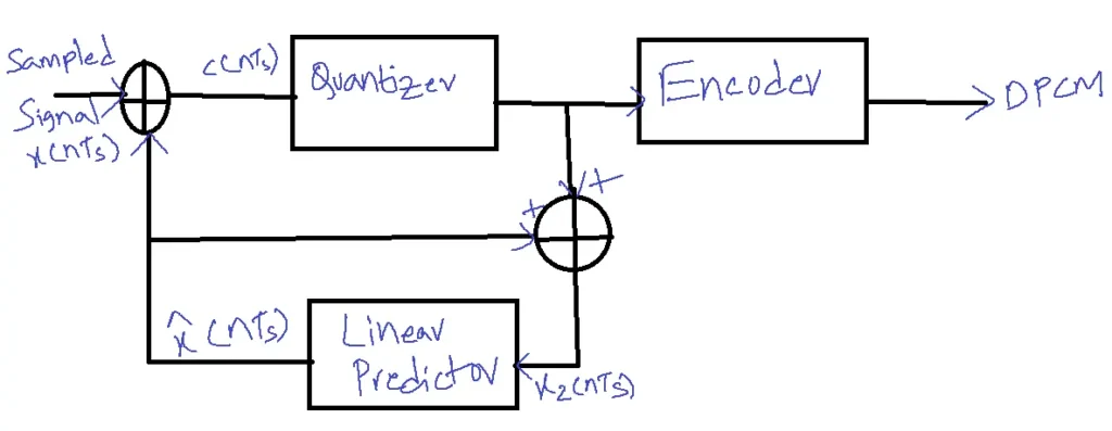
Differential Pulse Code Modulation(DPCM):
Typical speech waveforms have sample-to-sample redundancies, exploited via differential pulse code modulation (DPCM). Instead of transmitting a binary code representing a single sample, DPCM transmits a binary code proportional to the difference in amplitude between two subsequent samples. Compared to traditional PCM, DPCM requires fewer bits because the range of sample differences is smaller than the range of individual sample amplitudes.
Block Diagram of DPCM:
Ex: x(n)={2.1, 2.2, 2.3, 2.4, 2.5, 2.6, 2.7, 2.8}
| x(nTs) | x^( nTs) | e(nTs)= x(nTs)- x^( nTs) | eq(nTs) | x2(nTs) | |
| n=0 | 2.1 | 0 | 2.1 | 2 | 2 |
| n=1 | 2.2 | 2 | 0.2 | 0 | 2 |
| n=2 | 2.3 | 2 | 0.3 | 0 | 2 |
| n=3 | 2.6 | 2 | 0.6 | 1 | 3 |
| n=4 | 2.7 | 3 | -0.3 | 0 | 3 |
| n=8 | 2.8 | 3 | -0.2 | 0 | 3 |
e(nTs)=x(nTs)-x^(nTs)
x(nTs)=x^(nTs)+ e(nTs)
input to the predator
xq(nTs)=x^(nTs)+ eq(nTs)
eq(nTs)-e(nTs)=epsilon(€)
eq(nTs)= epsilon(€)+e(nTs)
xq(nTs)=x^(nTs)+ eq(nTs)+ €
xq(nTs)=x(nTs)+ €
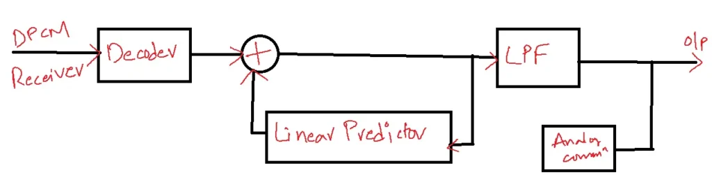
DPCM Receiver:
| n | Received Sample | x^(nTs) output of predator | Approximate Signal |
| 0 | 2 | 0 | 2 |
| 1 | 0 | 2 | 2 |
| 2 | 0 | 2 | 2 |
| 3 | 1 | 2 | 3 |
| 4 | 0 | 3 | 3 |
| 8 | 0 | 3 | 3 |
Problem: A signal whose amplitude varies from 0 to 10 V is Band limited to 4 KHz and transmitted through a channel using a 5-bit PCM system. The sampling risk is 50% higher than the Nyquist rate. Calculate all parameters of the PCM system.
Solution: L=2n=25=32
fs=3/2 X 8 KHz =12 KHz
Nyquist rate=2W=8KHz
step size = Vmax-Vmin/L=10-0/32
Number of samples per second X number of bits per sample is Rb
=N X fs
=5 x 12=60 Kilobits/second
BW≥Rb/2
BW≥30 KHz
Applications of Pulse Code Modulation:
- Digital Voice Transmission:
- PCM is the foundation for digital voice transmission over satellite links. It converts analog voice signals into digital data, allowing for efficient transmission, error correction, and integration with other digital communication systems.
- Digital Audio Broadcasting (DAB):
- PCM is used in DAB to transmit high-quality digital audio signals via satellite. This enables the delivery of radio broadcasts with improved sound quality, wider coverage, and additional features like program information and station identification.
- Digital Video Broadcasting (DVB):
- PCM is employed in DVB systems to transmit digital video signals over satellite. This allows for high-definition (HD) and ultra-high-definition (UHD) television broadcasts with superior picture quality and the potential for interactive services.
- Data Communication and Telemetry:
- Satellites transmit data and telemetry to ground stations using PCM. This includes sensor data, spacecraft health monitoring, and scientific measurements, contributing to various applications like weather forecasting and Earth observation.
- Encryption and Secure Communication:
- PCM can be combined with encryption techniques to secure satellite communications. This is crucial for military applications, government communications, and other sensitive data transmissions where confidentiality and integrity are paramount.
Related FAQs
1. What is Pulse Code Modulation (PCM) and how does it work in satellite communication?
- PCM is a digital modulation technique that converts analog signals (e.g., voice, video) into a digital format for transmission over satellite links.
- It involves sampling the analog signal, quantizing the samples, and encoding them into binary code.
2. Why is PCM used in satellite communication?
- PCM offers several advantages over analog modulation in satellite communication, including improved signal quality, noise immunity, error correction capabilities, and efficient bandwidth usage.
- It also enables the integration of voice, video, and data on a single platform.
3. What are the main components of a PCM system in satellite communication?
- A PCM system in satellite communication typically consists of a PCM encoder (transmitter) at the ground station, a satellite transponder, and a PCM decoder (receiver) at the receiving end.
- The encoder converts analog signals to digital, while the decoder converts digital signals back to analog.
4. What are the different types of PCM used in satellite communication?
- Satellite communication utilizes various forms of PCM, including standard PCM, differential PCM (DPCM), and adaptive differential PCM (ADPCM).
- These variations offer different trade-offs between complexity, signal quality, and bandwidth efficiency.
5. What hurdles does PCM encounter in satellite communication, and what advancements can we anticipate in the future?
- Challenges include bandwidth limitations and the need for accurate synchronization between the transmitter and receiver.
- Future trends involve utilizing more advanced modulation techniques, such as QAM (Quadrature Amplitude Modulation), to improve spectral efficiency and data rates.