
- In Network Topology, a Graph is obtained by replacing each resistor, capacitor, and inductor with a line segment.
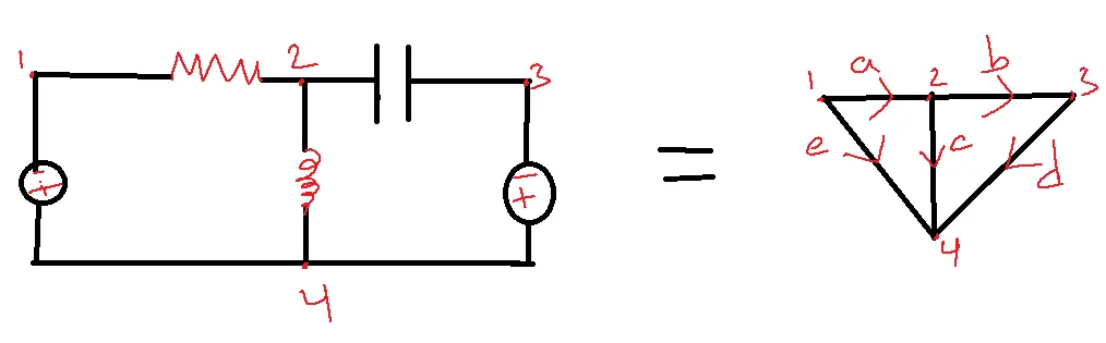
- An oriented graph is nothing but when directions are given to the graph.
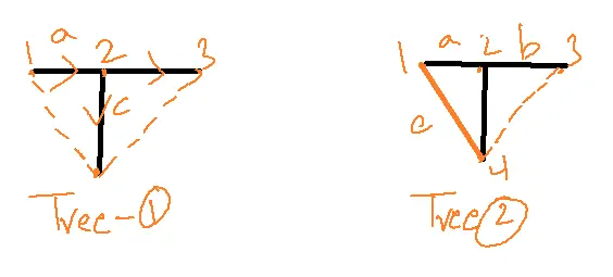
- The tree can be obtained by removing branches.
- The tree is a part of a graph containing all the nodes without any closed path.
Different possibilities for a given graph= det[[Ar][Ar]T]
Ar– Reduce incidence matrix
A- Incidence matrix
Ar- by deleting any row in A.
Table of Contents
Incidence Matrix of Network Topology:
- The incidence Matrix of Network Topology is obtained from the directed graph.
- Sign +1, if the arrow of the branch is oriented away from the node.
- -1 in the matrix if the arrow of the branch is oriented towards a node.
- Assign 0 in the matrix if the branch is not connected to a node.
| a | b | c | d | e | |
| 1 | 1 | 0 | 0 | 0 | 1 |
| 2 | -1 | 1 | 1 | 0 | 0 |
| 3 | 0 | -1 | 0 | -1 | 0 |
| 4 | 0 | 0 | -1 | -1 | -1 |
Properties of Incidence Matrix:
1. The sum of any column is zero.
2. The determinant of any closed loop is zero.
Ar= 1 0 0 0 1
-1 1 1 0 0
0 -1 0 1 0 3 x 5
ArT= 1 -1 0
0 1 -1
0 1 0
0 0 1
1 0 0 5 x 3
Ar X ArT=2(6-1)+1(-2)
=10-2=8.
Twigs are branches that correspond to trees.
Co-Tree: The branches removed from the graph to get a tree are called links or chords.
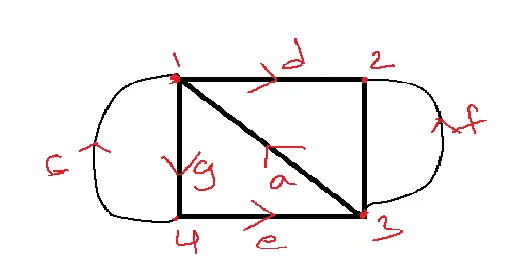
Obtaining Graph from Incident Matrix:
| a | b | c | d | e | f | g | |
| 1 | -1 | 0 | -1 | 1 | 0 | 0 | 1 |
| 2 | 0 | -1 | 0 | -1 | 0 | -1 | 0 |
| 3 | 1 | 1 | 0 | 0 | -1 | 1 | 0 |
| 4 | 0 | 0 | 1 | 0 | 1 | 0 | -1 |
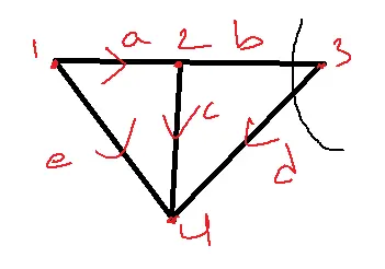
Tie Set Matrix
The Tie Set matrix of the network topology gives the relation between link currents and branch currents.
| ja | jb | jc | jd | je | |
| a | b | c | d | e | |
| Ie | 1 | 0 | 1 | 0 | -1 |
| id | 0 | 1 | -1 | 1 | 0 |
Ja=ie, jb=ib, jc=ie-id, jd=id,je=-ie
Cut Set Matrix of Network Topology
In cut set matrix of network topology
Number of rows=Number of twigs
Number of columns = Number of branches.
Duality
Dual elements
V –. I
R –. G
L –. C
KCL – KVL
Open circuit – short circuit
Series – Parallel
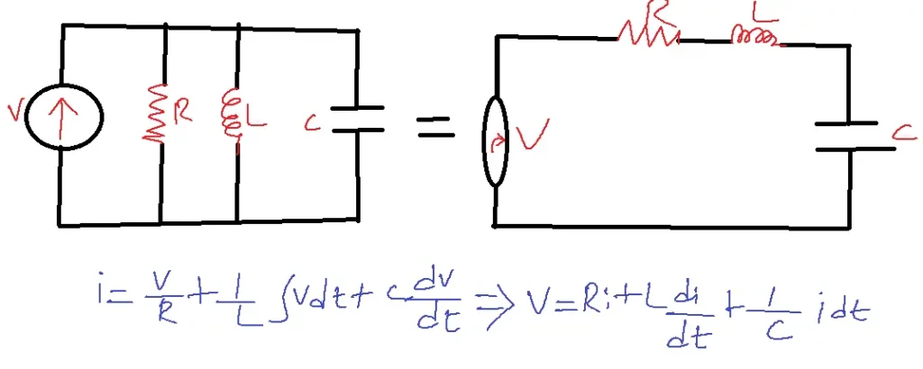
If two circuits have the same describing equations but different dual quantities, they are said to be dual to each other.
Cut Set Matrix :
Number of rows = Number of twigs
Number of columns = Number of branches
Tie-Set Matrix Formation :
1. Select a tree and co-tree from the directed graph.
2. Determine the number of links.
3. Number of tie set currents = Number of links.
4. Assign tie set currents thus they only pass through one path connection.
5. The direction of the tie set current is the same as the direction of the link.
6. Assign +1 in a matrix, if the directions of the tie set current and branch are the same.
7. -1 otherwise.
8. Assign 0 if the tie set current does not flow through the branch.
Cut Set Matrix formation:
1. Select a tree and co-tree from the directed graph.
2. Determine the Number of twigs.
3. Number of cut sets = Number of twigs.
4. A cut set may contain any number of links but it should contain only one link.
5. A cut set is oriented in the same direction as the twig it covers.
6. Assign +1 in the matrix if the directions of the cut set and branches are the same.
7. -1 if the directions are opposite.
8. 0 in the matrix if the cut set does not cover the branch.
Cut Set Matrix: A matrix represents the relation between cut sets and several branches in a directed graph.
Tie Set Matrix: Gives the relation between the number of link currents and several branch currents in a directed graph.
Applications of Network Topology
1. Circuit Analysis and Design:
- Electrical circuits can be seen using network topology, which breaks complex systems into nodes and branches.
- This makes it easy to conduct analysis using techniques such as Kirchhoff’s laws and nodal analysis.
- Engineers can maximize circuit designs in terms of efficacy, dependability, and affordability.
2. Systems for Distributing Power:
- Network topology knowledge aids in the creation of effective power distribution systems for commercial, residential, and industrial settings.
- Reliable power transmission and loss minimization are ensured by selecting the appropriate topology (radial, ring, or mesh).
- Faster power restoration during outages is made possible by topology, which helps with fault separation and identification.
3. Communication Networks:
- Network topology is essential for developing communication networks including the Internet, LANs, and WANs.
- Network topologies, such as bus, star, ring, and mesh, each offer distinct levels of redundancy, scalability, and performance.
- Topology analysis is instrumental in managing network traffic and optimizing data routing for efficient communication.
4. Electrical Safety and Grounding:
- Proper grounding prevents shocks and device damage.
- Effective grounding systems are designed with network structure in mind, providing optimal current flow and voltage equalization.
- This is critical in-home wiring, industrial facilities, and lightning protection systems.
5. Smart Grids and Renewable Energy Integration:
- Using renewable energy sources like solar and wind power in a modern smart grid requires network topology.
- Topology facilitates the management of bidirectional power flow, energy storage systems, and demand response programs.
- It increases sustainability and reliability by enabling effective grid-wide monitoring, control, and optimization.
Related FAQs
Q1. What is network topology in electrical engineering, and why is it important?
- Network topology refers to how various elements (devices, nodes, links) are organized and interconnected within an electrical network.
- It’s crucial because it impacts the network’s performance, reliability, and cost.
- Understanding topology helps engineers design and analyze circuits, power systems, and communication networks for optimal functionality and efficiency.
Q2. What are the different types of network topologies used in electrical engineering?
- Common topologies include bus, star, ring, mesh, tree, and hybrid configurations.
- Each topology has unique advantages and drawbacks in cost, scalability, fault tolerance, and ease of installation.
- The choice depends on the specific application and requirements.
Q3. How does network topology affect the reliability and performance of electrical systems?
- Network topology significantly influences reliability and performance.
- For instance, a mesh topology offers high redundancy and fault tolerance, ensuring continuous operation even if some links fail.
- In contrast, a bus topology is susceptible to single-point failures.
- Additionally, topology influences signal transmission speed, latency, and bandwidth within communication networks.
Q4. How is network topology used in designing power distribution systems?
- In power distribution, topology determines how electricity is delivered from the source to consumers.
- Radial, ring, and mesh topologies are commonly used, each with different levels of reliability and cost.
- Engineers choose the topology based on load demand, geographic coverage, and desired fault tolerance.
Q5. What are the applications of network topology in communication networks and smart grids?
- Network topology is crucial in communication networks, determining how data flows between devices and influencing network speed and reliability.
- In smart grids, topology helps integrate renewable energy sources, manage bidirectional power flow, and optimize energy distribution for improved efficiency and sustainability.