
Multiplexers and demultiplexers are combinational circuits with opposite purposes in digital data processing. Multiplexer selects and consolidates data, while Demultiplexer distributes and expands data.
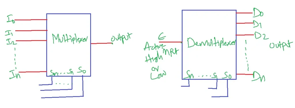
Table of Contents
Multiplexers
Multiplexer is a combinational circuit that selects 1 out of 2n inputs and directs it to the output specified by n select lines.
Multiplexer is also known as MUX.
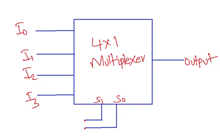
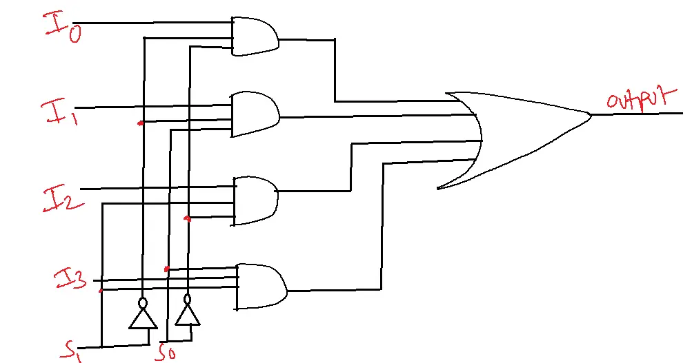
4 X 1 Multiplexer
Truth table
| Input | Input | Output |
| 0 | 0 | I0 |
| 0 | 1 | I1 |
| 1 | 0 | I2 |
| 1 | 1 | I3 |
Logic Diagram
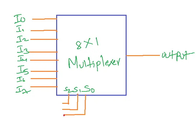
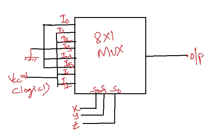
8 X 1 Multiplexer
Truth Table
| S0 | S1 | S2 | OUTPUT |
| 0 | 0 | 0 | I0 |
| 0 | 0 | 1 | I1 |
| 0 | 1 | 0 | I2 |
| 0 | 1 | 1 | I3 |
| 1 | 0 | 0 | I4 |
| 1 | 0 | 1 | I5 |
| 1 | 1 | 0 | I6 |
| 1 | 1 | 1 | I7 |
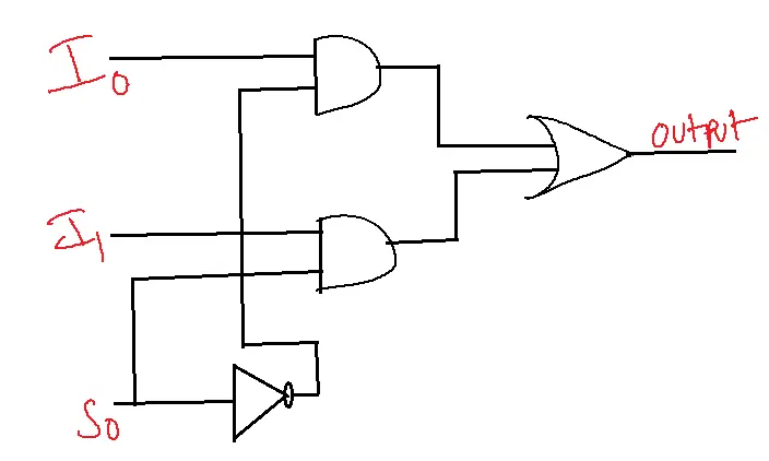
2 X 1 Multiplexer
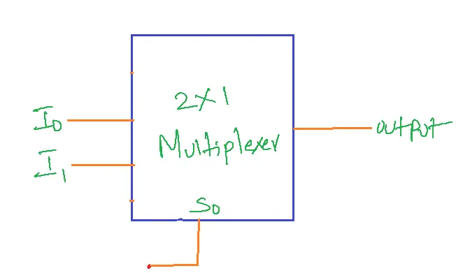
Truth table
| S0 | OUTPUT |
| 0 | I0 |
| 1 | I1 |
Logic Diagram
Problems
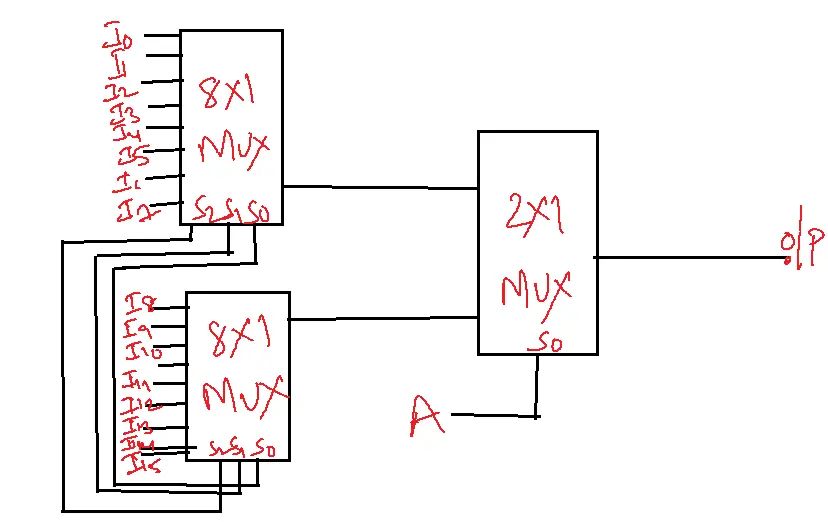
Construct a 16 X 1 MUX with two 8 X 1 MUX and one 2 X 1 MUX
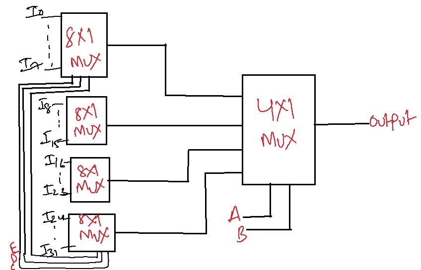
Construct 32 X 1 MUX with 4 8 X 1 MUX and 1 4 X 1 MUX.
Realization of Boolean function with MUX
n variable Boolean function
1. 2n:1 ( No external gates)
2. 2n-1:1 (NOT gates)
3. 2n-2:1 (AND, OR/NOT Gates)
F(x,y,z)=∑m(1,2,6,7)
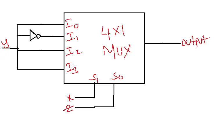
Using 8 X 1 MUX
Using 4 X 1 MUX
xy as select lines and z as input data line.
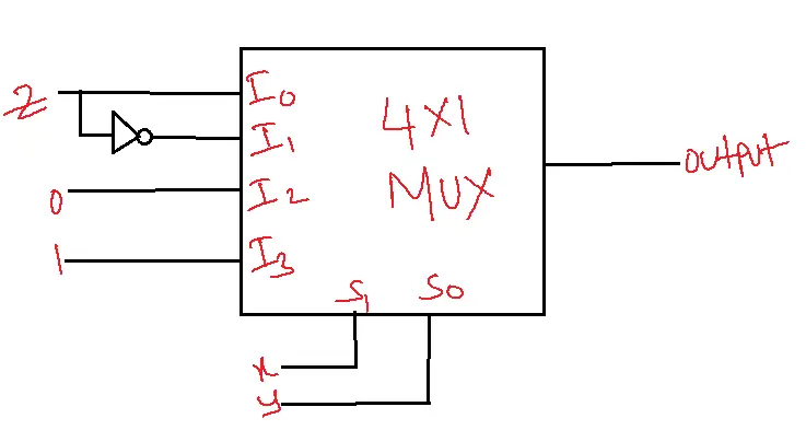
| I0 | I1 | I2 | I3 | |
| Z’ | 0 | 2 | 4 | 6 |
| Z | 1 | 3 | 5 | 7 |
xz as the select line and y as the input data line
| I0 | I1 | I2 | I3 | |
| y’ | 0 | 1 | 4 | 5 |
| y | 2 | 3 | 6 | 7 |
Problem: An 8 X1 MUX has inputs A, B, and C connected to the selection lines s2,s1, and s0 respectively.
Data inputs I0 to I7 has I1=I2=I7=0, I3=I5=1, I0=I4=D, I6=D’. Determine the Boolean function that the mux implements.
Solution:
| I0 | I1 | I2 | I3 | I4 | I5 | I6 | I7 | |
| D’ | 0 | 2 | 4 | 6 | 8 | 10 | 12 | 14 |
| D | 1 | 3 | 5 | 7 | 9 | 11 | 13 | 15 |
| D | 0 | 0 | 1 | D | 1 | D’ | 0 |
F(A, B, C, D) = ∑m(1,6,7,9,10,11,12)
Advantages of Multiplexer
1. Reduced wiring and cost: MUX requires fewer wires and connections, so a multiplexer is more affordable.
2. Increased efficiency: MUX allows multiple signals to share the same transmission line, increasing efficiency.
3. Improved scalability: Adding or removing input signals without changing the circuit as a whole is made simple by MUX.
4. Simplified circuit design: MUX simplifies circuit design by reducing the number of components and connections.
5. Fast data transfer: Multiple signals can be carried over a single line thanks to MUX, which allows for quick data transfer rates.
Disadvantages of Multiplexer
1. Complexity: MUX can be complex to design and implement, especially for large numbers of input signals.
2. Signal distortion: MUX can introduce a signal distortion or attenuation, affecting signal quality.
3. Limited bandwidth: MUX can limit the bandwidth of the output signal, affecting high-frequency signals.
4. Power consumption: MUX can consume more power than demultiplexers (DEMUX), especially in large circuits.
5. Error susceptibility: MUX is susceptible to errors due to faulty selection lines or input signals.
Applications
1. Data Selection: MUX selects data from multiple sources and sends it to a single destination, which is useful in data processing and transmission.
2. Analog-to-Digital Conversion: MUX helps select analog signals for conversion to digital signals.
3. Digital Signal Processing: MUX enables the selection of different digital signals for processing.
4. Communication Systems: MUX increases data transmission efficiency by allowing multiple signals to share a single communication channel.
5. Computer Networks: MUX manages data transmission between multiple devices in a network.
6. Audio/Video Switching: MUX switches between multiple audio or video sources for display or recording.
7. Error Detection and Correction: MUX helps select data for error detection and correction.
8. Memory Management: MUX selects data for storage or retrieval from memory.
9. Digital Logic Circuits: MUX implements digital logic circuits like encoders, decoders, and adders.
10. Medical Equipment: MUX is used in devices like ECG, EEG, and patient monitoring systems.
11. Aerospace Engineering: MUX is used in navigation, control, and communication systems.
12. Automotive Systems: MUX used in infotainment, navigation, and safety systems.
DEMULTIPLEXER
A Decoder with enabled input is a demultiplexer.
Demultiplexer is a combination circuit that transfers the data from a single input line to one of 2n output lines selected by n select lines.
Demultiplexer is also known as DEMUX.
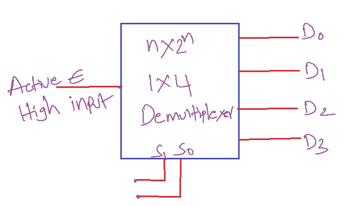
Truth table for Active High Input
| E | S0 | S1 | D0 | D1 | D2 | D3 |
| 0 | X | X | 0 | 0 | 0 | 0 |
| 1 | 0 | 0 | 1 | 0 | 0 | 0 |
| 1 | 0 | 1 | 0 | 1 | 0 | 0 |
| 1 | 1 | 0 | 0 | 0 | 1 | 0 |
| 1 | 1 | 1 | 0 | 0 | 0 | 1 |
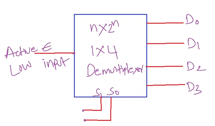
Truth table for Active Low Input
| E | S0 | S1 | D0 | D1 | D2 | D3 |
| 1 | X | X | 1 | 1 | 1 | 1 |
| 0 | 0 | 0 | 0 | 1 | 1 | 1 |
| 0 | 0 | 1 | 1 | 0 | 1 | 1 |
| 0 | 1 | 0 | 1 | 1 | 0 | 1 |
| 0 | 1 | 1 | 1 | 1 | 1 | 0 |
Applications of Demultiplexer
1. Data Distribution: DEMUX distributes data from a single source to multiple destinations.
2. Digital Signal Processing: DEMUX enables routing digital signals to specific processing units.
3. Communication Systems: DEMUX separates and routes incoming data to respective channels or devices.
4. Computer Networks: DEMUX directs data to specific nodes or devices in a network.
5. Memory Management: DEMUX routes data to specific memory locations.
6. Digital Logic Circuits: DEMUX implements digital logic circuits like decoders and demodulators.
7. Error Detection and Correction: DEMUX helps route data for error detection and correction.
8. Audio/Video Routing: DEMUX routes audio or video signals to specific output devices.
9. Medical Equipment: DEMUX is used in medical devices like patient monitoring systems and medical imaging.
10. Aerospace Engineering: DEMUX is used in navigation, control, and communication systems.
11. Automotive Systems: DEMUX is used in infotainment, navigation, and safety systems.
12. Data Decoding: Data can be decoded from a single source into several forms using DEMUX.
13. Digital Television: DEMUX is used in digital TV receivers to separate and route audio and video signals.
14. Networking Switches: DEMUX is used in networking switches to route data to specific ports.
Key differences
1. Direction: MUX combines multiple inputs into one output, while DEMUX takes one input and splits it into different outputs.
2. Functionality: MUX selects one input signal, while DEMUX directs the input signal to one of multiple outputs.
3. Number of inputs/outputs: MUX has multiple inputs and one output, while DEMUX has one input and multiple outputs.
4. Application: MUX is used for data compression, while DEMUX is used for data expansion.
5. Complexity: DEMUX is generally less complex than MUX, as it only requires a simple switching mechanism.
Similarities
1. Both are electronic circuits used for signal processing.
2. Both have multiple inputs and outputs.
3. Both use control signals to manage data flow.
FAQs
1. What is a multiplexer (MUX)?
- A multiplexer, often shortened to MUX, is a combinational logic circuit that selects one of several input lines and forwards it to a single output line based on the selected signals.
- It acts as a digital switch, enabling data selection and routing in various applications.
2. What is a demultiplexer (DEMUX)?
- A demultiplexer, or DEMUX, performs the opposite function of a MUX.
- t takes a single input line and distributes it to one of several output lines based on the select signals.
- It acts as a data distributor, enabling signal routing to different destinations.
3. What are the main differences between a multiplexer and a demultiplexer?
- Function: MUX selects one input out of many; DEMUX distributes one input to many outputs.
- Data Flow: MUX has multiple data inputs and one output; DEMUX has one data input and various outputs.
- Select Lines: Both use select lines to control the data path, but MUX’s select lines determine which input is connected to the output, while DEMUX’s select lines determine which output receives the input.
4. What are the applications of multiplexers and demultiplexers?
- Communication systems: Used in time-division multiplexing (TDM) to combine multiple signals onto a single transmission line and separate them at the receiving end.
- Data acquisition systems: MUXs select data from multiple sensors, while DEMUXs route data to different processing units.
- Memory addressing: MUXs select the appropriate memory location based on address lines.
- Digital displays: DEMUXs control which segments of a display are illuminated.
- Logic function implementation: MUXs can be used to implement Boolean functions.
5. How do I choose the right multiplexer or demultiplexer?
- Consider these factors:
- Number of inputs/outputs: Select a MUX/DEMUX with the required input and output lines.
- Select lines: The number of select lines determines how many inputs/outputs the device can handle (2^n, where n is the number of select lines).
- Propagation delay: Choose a device with a suitable propagation delay for your application’s speed requirements.
- Power consumption: Consider the device’s power consumption, especially for battery-powered applications.