
Introduction to Logic Gates
Logic gates are the basic building blocks of digital electronics and computer systems. They are electronic circuits that perform logical operations on one or more input signals to produce an output signal.
Logic gates take binary inputs (0s and 1s) and produce a binary output based on a specific logical operation, such as:
1. AND (Conjunction)
2. OR (Disjunction)
3. NOT (Negation)
4. NAND (NOT AND)
5. NOR (NOT OR)
6. XOR (Exclusive OR)
7. XNOR (Exclusive NOR)
Table of Contents
In digital electronic circuits, these logical processes are used to calculate, make judgments, and regulate the data flow.
Logic gates are typically represented by symbols, such as:
– AND: ∧ or ·
– OR: ∨ or +
– NOT:!
They can be implemented using various technologies, including:
1. Digital ICs (Integrated Circuits)
2. Programmable Logic Devices (PLDs)
3. Transistors
4. Diodes
Logic gates are the foundation of digital logic design, and their combinations enable the creation of complex digital circuits and systems.
Logic Gates are of three types:
- BASIC LOGIC GATES
- AND Gate
- OR Gate
- NOT Gate
- UNIVERSAL LOGIC GATES
- NAND Gate
- NOR Gate
- OTHER GATES
- EX-OR Gate
- EX-NOR Gate
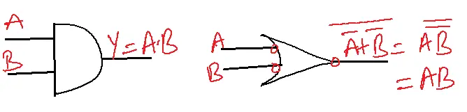
AND GATE
SYMBOL
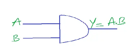
FUNCTION
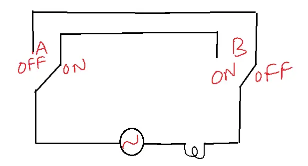
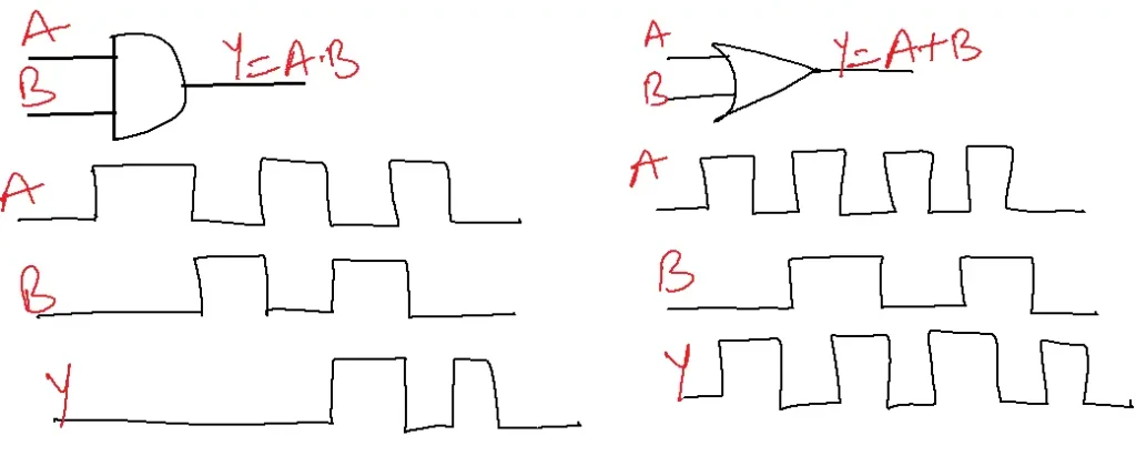
The output of the AND gate is high, if all its inputs are high. Or output is low if at least one input is low.
Truth table
1. The gate takes two or more input signals (A and B).
2. If both inputs are 1 (true), the output is 1 (true).
3. If any input is 0 (false), the output is 0 (false).
| A | B | Y |
| 0 | 0 | 0 |
| 0 | 1 | 0 |
| 1 | 0 | 0 |
| 1 | 1 | 1 |
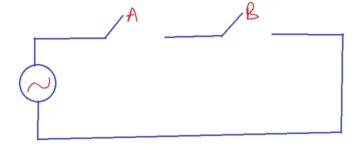
Electrical equivalent circuit(switching circuit)
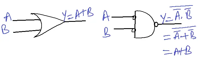
OR GATE
SYMBOL
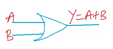
FUNCTION
The output of the OR gate is high if at least one of its inputs is high. Or output is low if all its inputs are low.
Truth table
1. If either input is 1, the output is 1.
2. Only if both inputs are 0, the output is 0.
| A | B | Y |
| 0 | 0 | 0 |
| 0 | 1 | 1 |
| 1 | 0 | 1 |
| 1 | 1 | 1 |
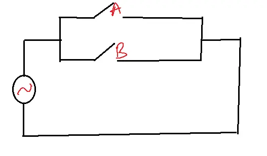
Electrical equivalent circuit
NOT GATE
SYMBOL
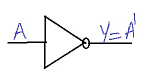
FUNCTION
The output of a NOT gate is the complement of the input.
Truth table
| A | Y |
| 0 | 1 |
| 1 | 0 |
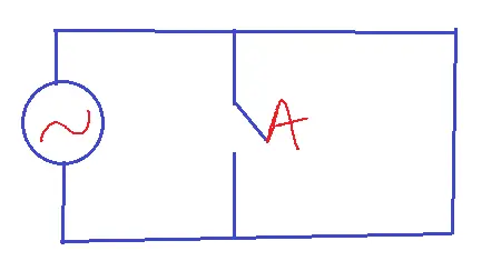
Electrical Equivalent Circuit
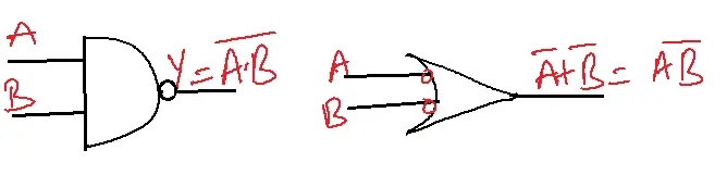
NAND GATE
SYMBOL
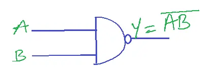
Function
Output is high if at least one input is low. Or the output is low, when all its inputs are at high.
Truth table
1. If both inputs are 1, the output is 0.
2. If either input is 0, the output is 1.
| A | B | Y |
| 0 | 0 | 1 |
| 0 | 1 | 1 |
| 1 | 0 | 1 |
| 1 | 1 | 0 |
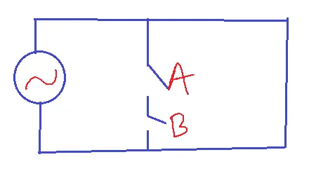
Equivalent circuit
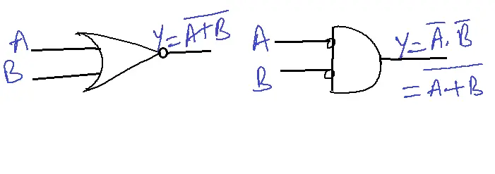
NOR Gate
Symbol
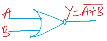
Function
Output is high if all its inputs are low. Or output is low if at least one input is high.
Truth table
1. If either input is 1, the output is 0.
2. Only if both inputs are 0, the output is 1.
| A | B | Y |
| 0 | 0 | 1 |
| 0 | 1 | 0 |
| 1 | 0 | 0 |
| 1 | 1 | 0 |
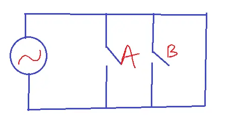
Electrical equivalent circuit
EX-OR GATE
SYMBOL
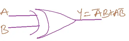
FUNCTION
Output is high if an odd number of inputs is high. Or output is low if the number of inputs is high.
Truth table
1. If inputs are different (one 0 and one 1), the output is 1.
2. If inputs are the same (both 0 or both 1), the output is 0.
| A | B | Y |
| 0 | 0 | 0 |
| 0 | 1 | 1 |
| 1 | 0 | 1 |
| 1 | 1 | 0 |
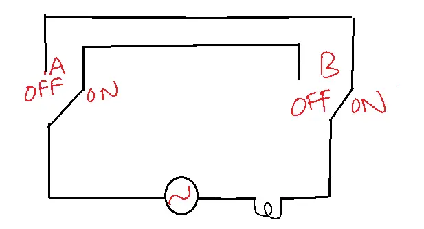
Electrical equivalent circuit
EX-NOR Gate
SYMBOL
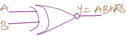
FUNCTION
Output is high, if inputs are the same. Or Output is low if inputs are different.
Truth table
1. If inputs are the same (both 0 or both 1), the output is 1.
2. If inputs are different (one 0 and one 1), the output is 0.
| A | B | Y |
| 0 | 0 | 1 |
| 0 | 1 | 0 |
| 1 | 0 | 0 |
| 1 | 1 | 1 |
Equivalent circuit
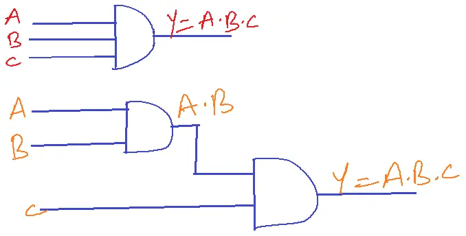
Multiple inputs of logic gates
Y= A.B.C
Y=A+B+C
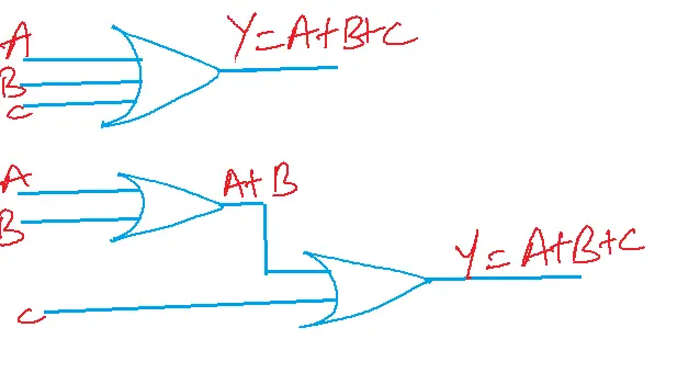
If two inputs give three inputs(multiple inputs) OR and AND gates must satisfy commutative associative law.
Inputs negated NOR gate is AND.
Inputs negated NAND gate is OR.
Inputs negated OR gate is NAND.
Inputs are negated in AND gate is NOR.
In gates, logic 1=5V, logic 0=0V.
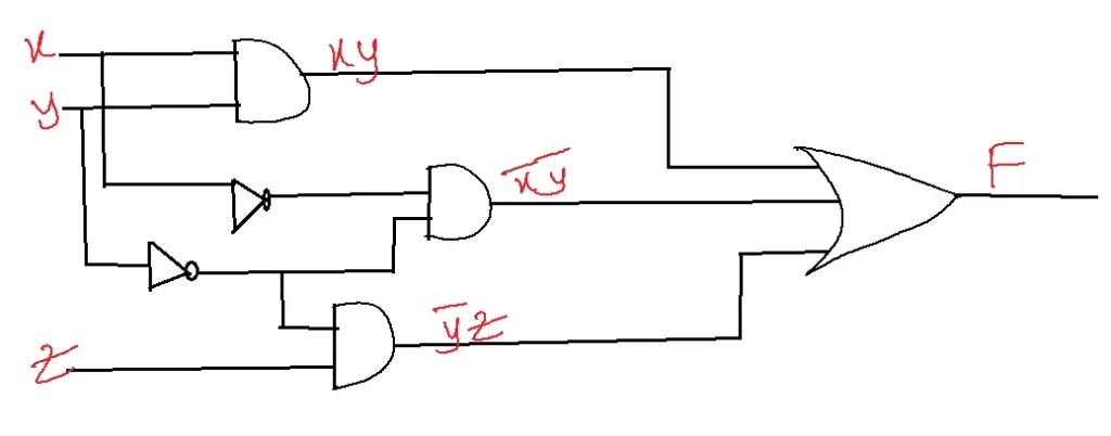
Implementation of Boolean function with logic gates
F=xy+x’y’+y’z implement with AND, OR, NOT
UNIVERSAL GATES
NAND, NOR – because any gate can be realized either with only NAND gates or only NOR gates.
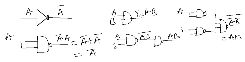
Implementation of NOT, AND, OR Gates with NAND Gates.
| Gate | Number of NAND Gates | Number of NOR Gates |
| 0 | 0 | 0 |
| 0 | 1 | 1 |
| 1 | 0 | 1 |
| 1 | 1 | 1 |
Advantages
1. Simplifies Complex Circuits: Logic gates break down complex digital circuits into simpler, manageable components.
2. Flexibility: Logic gates can be combined to create a variety of digital circuits.
3. Modularity: Modular design, made possible by logic gates, facilitates the scalability and flexibility of digital circuitry.
4. Easy Implementation: Logic gates are easy to implement using digital ICs or programmable logic devices.
5. Fast Operation: These gates operate at high speeds, enabling fast data processing.
6. Low Power Consumption: These gates consume low power, making them suitable for energy-efficient designs.
7. Scalability: These gates can be used to design circuits with varying levels of complexity.
8. Error Detection and Correction: These gates facilitate detection and correction in digital circuits.
9. Code Conversion: These gates enable conversion between different number systems (e.g., binary to decimal).
10. Fundamental Building Blocks: These gates are the basic building blocks of digital electronics and computer systems.
Disadvantages
1. Limited Functionality: Individual logic gates have limited functionality, requiring multiple gates to perform complex operations.
2. Complexity: Large-scale digital circuits can become complex and difficult to manage.
3. Propagation Delay: These gates introduce propagation delay, affecting the speed of digital circuits.
4. Power Consumption: Even though the logic gate is low, power consumption in large-scale digital designs might still be an issue.
5. Cost: Implementing these gates using digital ICs or programmable logic devices can be costly.
6. Design Challenges: Designing and optimizing logic gate circuits can be time-consuming and require expertise.
7. Fan-out Limitations: Logic gates have limited fan-out capacity, restricting the number of gates that can be driven.
8. Noise Sensitivity: These gates can be sensitive to noise, affecting their reliability.
9. Limited Scalability: As digital circuits grow, logic gate-based designs can become less scalable.
10. Obsolescence: Logic gate-based designs could become antiquated as technology advances.
Applications of Logic Gates
1. Digital Circuits: These gates are applied to create complex digital circuits, such as arithmetic logic units (ALUs), counters, and registers.
2. Computer Processors: These gates are the foundation of central processing units (CPUs) and graphics processing units (GPUs).
3. Electronic Devices: Logic gates are used in various electronic devices, including smartphones, tablets, and laptops.
4. Control Systems: Control systems like elevators and traffic light controllers use logic gates.
5. Data Storage: Logic gates are used in memory devices, such as RAM and ROM.
6. Digital Signal Processing: Logic gates are used in digital signal processing applications, such as audio and image processing.
7. Cryptography: Logic gates are used in cryptographic techniques, such as encryption and decryption.
8. Artificial Intelligence: Logic gates are used in artificial intelligence and machine learning applications, such as neural networks.
9. Medical Devices: Medical equipment like blood pressure and heart rate monitors use logic gates.
10. Aerospace Engineering: Logic gates are used in aerospace engineering applications, such as navigation and control systems.
FAQs
1. What are logic gates?
- Logic gates are the fundamental building blocks of digital circuits.
- They perform basic logical operations on one or more binary inputs to produce a single output.
2. What are the basic types of logic gates?
- The three basic logic gates are:
- AND gate: Outputs a 1 only when all inputs are 1.
- OR gate: Outputs a 1 if at least one input is 1.
- NOT gate: Inverts the input signal (0 becomes 1, 1 becomes 0).
3. What are the universal logic gates?
- NAND gate (NOT-AND) and NOR gate (NOT-OR) are called universal gates because they can be combined to create any other logic gate.
4. What are the applications of logic gates?
- Logic gates are used extensively in digital electronics for various applications including:
- Design sophisticated digital circuits, including adders, subtractors, multiplexers, and decoders.
- Engineering flip-flops and registers for memory storage.
- Microprocessors and microcontrollers enable the implementation of control and decision-making circuits.
5. How are logic gates represented?
- Logic gates are represented using
- Symbols: Unique shapes for each gate type (e.g., AND gate is a D-shape, OR gate is a curved shape).
- Truth tables: Tables showing all possible input combinations and their corresponding outputs.
- Boolean expressions: Algebraic expressions representing the logical operation of the gate.