
BJT is a non-linear device. To analyze a non-linear device that is complex, hence non-linear characteristics of BJT are approximated into linear characteristics and this approximation is possible only in small signals. The small signal model is also called the h-parameter or hybrid parameter model.
The BJT h-parameter model is based on the definition of hybrid parameters. The mathematical model for two-port networks known as the h-parameter model (Hybrid Parameter model) can be developed.
Table of Contents
The transistor is a two-port network. The transistor is also a current-operated device.
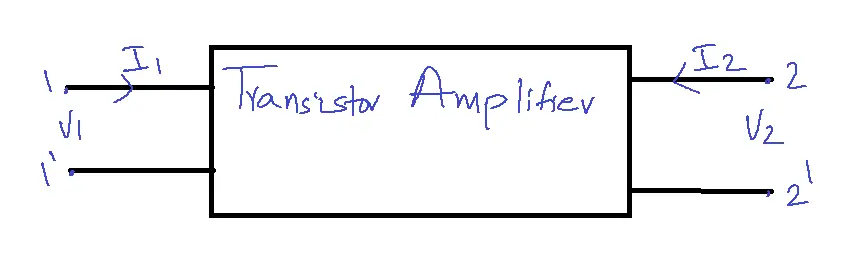
V1 = h11I1 + h12I2→1
I2 = h21I1 + h22V2→2
Consider I1, V2 as independent variables and V1, and I2 as dependent variables.
h11 = V1/I1 | V2=0 — short circuit input impedance = hi = hie
h12 = V1/V2 |I1=0 — open circuit reverse voltage gain = hr = h re
h21= I2/I1 | V2=0 –short circuit forward gain = hf = hfe
h22 = I2/V2 | I1=0 — open circuit output admittance= h0=h0e
Advantages of h-parameter model:
1. h-parameters are real numbers at audio frequencies.
2. The h-parameter model is easy to measure.
3. The h-parameter model can be calculated from the transistor static characteristic current.
4. The h-parameter model can be used in circuit analysis and design.
5. The h-parameter model can be easily convertible from one configuration to another.
6. Transistors manufacturers specify the values of h-parameters.
Typical Values of h-parameters:
| Parameter | Common emitter(CE) | Common collector(CC) | Common Base(CB) |
| hi | 1100 ohm | 1100 ohm | 22 ohm |
| hr | 2.5 x 10⁻⁴ | 1 | 3 x 10⁻⁴ |
| hf | 50 | 51 | -0.98 |
| h0 | 25 µA/v | 25 µA/v | -0.49 µA/v |
Input voltage = Vi
Input current = ii
Output voltage = V0
Output current = i0
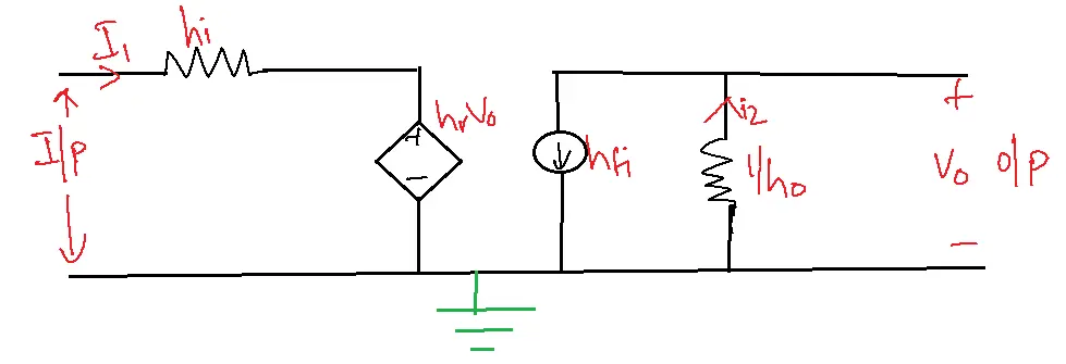
Vi= hiIi + hrV0 →3
I0= hfIi + h0V0 →4
Design a circuit with 3 and 4 we get the h-parameter model.
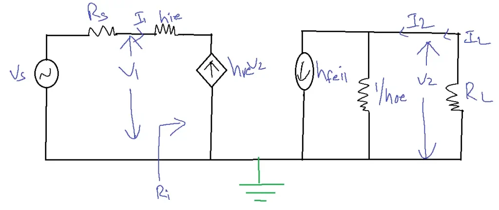
Draw an h-parameter model to common emitter configuration (Analysis):
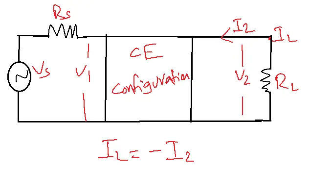
A transistor amplifier can be constructed by connecting an external load and signal source as indicated in the below figure and biasing the transistor properly.
The h-parameter also known as the hybrid parameter model is shown below figure:
1. Current gain AI: The current gain of a transistor amplifier is defined as the ratio of the output current to the input current, indicating the amplification factor.
AI = IL/I1 = – I2/I1
I2= hfeI1 + h0eV2
V2= ILRL = – I2 RL
I2 = hfeI1 + h0e( – I2 RL)
AI = -hfe/1+hoeRL
2. Input Resistance or Input Impedance:
Ri=V1/I1
V1=hieI1+hreV2
V1/I1 = hie+V2/I1
V2= ILRL
Ri = hie + hre AIRL
3. Voltage gain(Av): The ratio of output voltage to input voltage gives the voltage gain of the transistor.
Av=Vo/Vi
=V2/V1
Av = AIRL/Ri
4. Output admittance (yo) :
To determine the current gain AI, we disregard RL (output load resistance) and set Vs (input voltage source) to zero, effectively making Rs (input source resistance) zero as well.
Io = I2/V2 | R2 =0, Vs=0
I2 = hfe I1 + hoe V2
Yo=hoe – hfehre/hie.
Ro = 1/Y0
5. Output admittance (Yos) :
0 = (Rs + hie)I1 + hreV2
I1/V2 = -hre / Rs + hie
Yos = hoe – hfehre/Rs + hie
6. Input resistance (ris or zis):
Ris = Rs + Ri
7. Voltage gain including the source (Avs) :
Avs = V2/Vs
= Av V1/Vs
V1 = Vs x Ri/Rs + Ri
Avs = AvRi/Rs + Ri
8. Current gain including source (AIS):
AIS = IL/Is
AIS = AI (Rs/Rs + RI)
9. Power gain (AP):
APC = AV X AI
AV = AI X RL/Ri
AP = AI2 RL / Ri
Problem:
A common emitter amplifier is drawn by a voltage source of internal resistance Rs = 800 ohm, load impedance RL = 1000 ohm the h-parameters are hie = 1 KΩ, hre = 2 X 10⁻⁴ hfe = 50, hoe = 25 µA/V. Determine AI, RI, AV, RO, Zis or Ris and Ros or Zos.
Solution: AI = -hfe / 1 + hoeRL = -50/1+25 X 10-6 X 1000 = -48.7805.
Ri = hie + hre AI RL
= 1 x 10³ + 2 X 10⁻⁴ X (-48.7805) X 1000
= 990.2439.
AV = AI RL / Ri
= (-48.7805 X 1000) / 990.2439
= -49.2611
R0 = 1/Y0
= -13.33 KΩ
Ris = Rs + Ri
= 800 + 990.2439
= 1790.2439
Ros = 1/ Yos
= -32727.2727.
Applications of h-parameter model:
- Transistor Amplifier Design: Transistor amplifier design, particularly for BJTs and FETs, heavily relies on the h-parameter model for comprehensive analysis and effective design. It simplifies the complex behavior of transistors, making it easier to determine gain, input/output impedance, and stability.
- Filter Design: H-parameters aid filter design (low-pass, high-pass, band-pass, band-stop) by predicting frequency response, attenuation, and phase shift.
- Small-Signal Analysis: The h-parameter model is ideal for analyzing the small-signal behavior of circuits. This is essential for understanding how circuits respond to small variations in input signals, which is crucial for linear circuit design.
- Feedback System Analysis: Engineers use H-parameters to assess and develop feedback systems. They help determine the loop gain, stability margins, and performance of feedback amplifiers and control systems.
- Matching Networks: The h-parameter model assists in designing matching networks that maximize power transfer between different stages of a circuit. This is particularly important in RF and microwave circuits where impedance matching is critical.
FAQs of the h-parameter model:
1. What is the h-parameter model?
- The h-parameter model (or hybrid parameter model) is a two-port network representation used to characterize linear electronic circuits.
- It describes the relationships between input and output voltages and currents using four h-parameters: h11, h12, h21, and h22.
2. Why is the h-parameter model used in electronics?
- The h-parameter model is popular for several reasons:
- Simplifies analysis: It simplifies the analysis of complex circuits, especially those involving transistors.
- Practical measurements: H-parameters are relatively easy to measure in the lab compared to other two-port parameters.
- Widely used: Manufacturers often provide h-parameters in transistor datasheets, making them readily available for design.
3. What do the h-parameters represent?
- h11 (Input Impedance): The input impedance seen at the input port when the output port is short-circuited.
- Reverse Voltage Gain (h12): This parameter quantifies the voltage at the input port relative to the output voltage when the input is left open.
- h21 (Forward Current Gain): The ratio of output current to input current when the output port is short-circuited.
- h22 (Output Admittance): The output admittance seen at the output port when the input port is open-circuited.
4. How are h-parameters used in circuit analysis?
- H-parameters are used to analyze various circuits, including:
- Transistor amplifiers: Determine gain, input/output impedance, and stability.
- Filters: Design and analyze the frequency response of different filter types.
- Feedback systems: Assess loop gain, stability, and overall performance.
5. What are the limitations of the h-parameter model?
- Frequency-dependent: H-parameters can vary with frequency, making them less accurate at higher frequencies.
- Small-signal model: They are only valid for small signal analysis, where the input signal does not significantly alter the operating point of the device.