
A feedback amplifier is an electronic amplifier that uses a portion of its output signal to feed into the input, creating a loop. This feedback loop can be either positive or negative.
Open loop system:
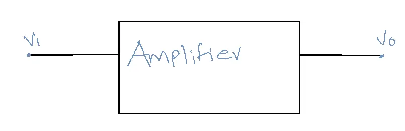
Here the gain A may change because of the following variations:
1. Temperature variations
2. Ag [using the transistor for a long time]
3. Replacement of existing device with another device.
These variations lead to an unstable system response.
To improve the amplifier’s stability, some portion of the output signal is again fed back to the input through a feedback network.
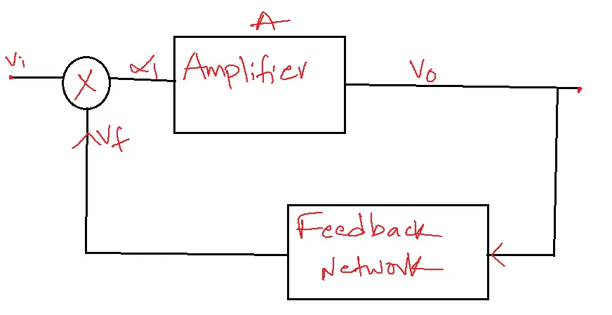
A = VO / Vi →gain without feedback.
β = Vf / VO
Gain with feedback Af = VO / Vs
Table of Contents
Types of feedback:
1. Positive Feedback
2. Negative Feedback
Positive Feedback:
If the feedback signal and input signal are in phase then that type of feedback is called positive feedback.
Positive feedback leads to amplified output signals, destabilizing the system and resulting in oscillatory behavior.
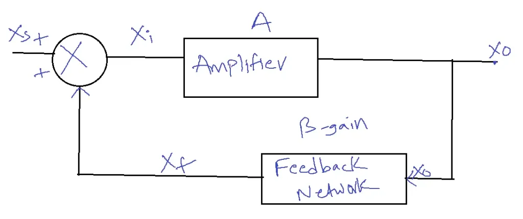
Gain with feedback Af = XO/Xs –1
Gain without feedback A = XO / Xi –2
Feedback gain β = Xf / XO –3
For positive feedback Xi = Xs + Xf –4
A/XO = Af/XO + β XO
From 1, Af = XO/Xs = XO/ Xi – Xf
= A/ 1- βA
Af = A/ 1- Aβ
Negative Feedback:
If the feedback signal and input signal are out of phase, that type of feedback is known as negative feedback.
Af = A/ 1 + Aβ
Example: The amplifier with negative feedback has Af = 120. It is found that based on input signal of 60 mv is required to produce a particular output, whereas with feedback the input signal must be 0.5V to get the same output. Find A and β of the amplifier.
Solution: Af = 120
Input = 60mv [input without feedback]
Af = VO / Vs
120 = VO / 0.5 à VO = 60.
A = VO / Vi
= 60 / 60mv
A = 1000
Af = A/ 1 + Aβ
120 = 1000 / 1 + 1000 β
β = 0.007.
Advantages of Negative Feedback Amplifier:
1. Negative feedback amplifier provides stabilization of gain.
2. It increases bandwidth.
We know that for Negative feedback Amplifiers,
Af = A/ 1 + Aβ
Af low = Alow / 1 + Alow β
Af high = Ahigh / 1 + Ahigh β
Af High or mid = Amid / 1 + Amid β
Lower cut-off frequency in Negative feedback Amplifier:
We know that
Alow = Amid/1-jfL/f
Af low = Alow / 1 + Alow β
Af low = Amid/1-jfLF/f
Where fLF = fL / 1 + Amid β
fLF→lower cut-off frequency with feedback.
By providing negative feedback, the lower cut-off frequency decreases.
fL = without feedback.
Upper cutoff frequency: (fHF)
We know that gain at high frequencies
Ahigh = Afmid/1-jf/fH
Af high = Ahigh / 1 + Ahigh β
Af high = Afmid/1-jf/fH
BW = fH – fL
BW = fHF – fLF
BWF = fHF =fH(1 + A β) fHF = higher cut off frequency with feedback
= BW(1 + A β)
Bandwidth with negative feedback = 1 + A β times
Bandwidth without feedback BWF = BW(1 + A β)
Negative feedback amplifier decreases noise:
The active device employed in an amplifier can significantly influence the types and levels of noise encountered.
With the use of this amplifier, the noise can be reduced as
Nf = N/1 +A β
Negative feedback decreases distortion:
Consider an amplifier with open loop voltage gain A and harmonic distortion D with the introduction of negative feedback, the distortion will be reduced to:
Df = D/1 +A β
Example: An amplifier has a mid-band gain of 125 and a bandwidth of 250 KHz.
i. If 4% negative feedback is introduced find new bandwidth and gain.
ii. If the bandwidth is restricted to 1MHz find the new feedback ratio.
Solution:
A=125, β= 0.04
i. Af = A/ 1 + A β = 20.33
BWF = BW(1 + A β) = 1.5 MHz
ii. BW = 1 MHz
BWF = BW(1 + A β’)
1 X 106 = 250 X 103 (1 + 125 β’)
β’= 1 X 10⁶/250 X 103 -1
β’= 24 %
Concept of Negative Feedback Amplifier:
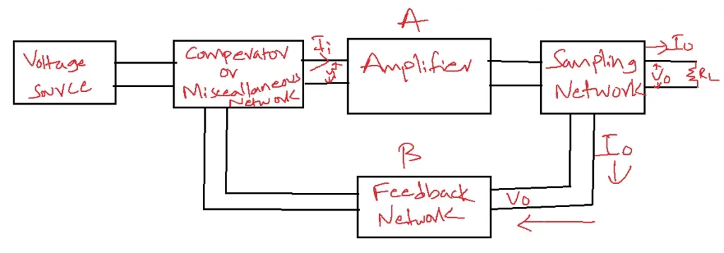
Sampling Network:
There are two types of sampling:
i. Voltage sampling
ii. Current sampling
Voltage Sampling and Current Sampling:
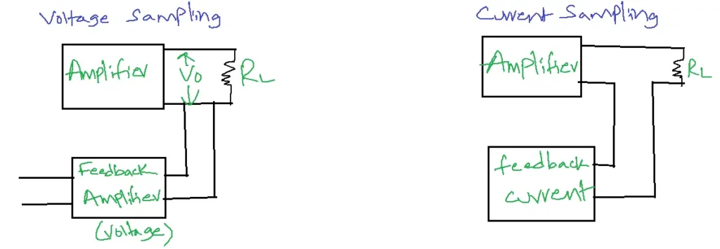
Feedback Network: The feedback network consists of passive elements. A portion of the output signal is again fed back through the feedback network.
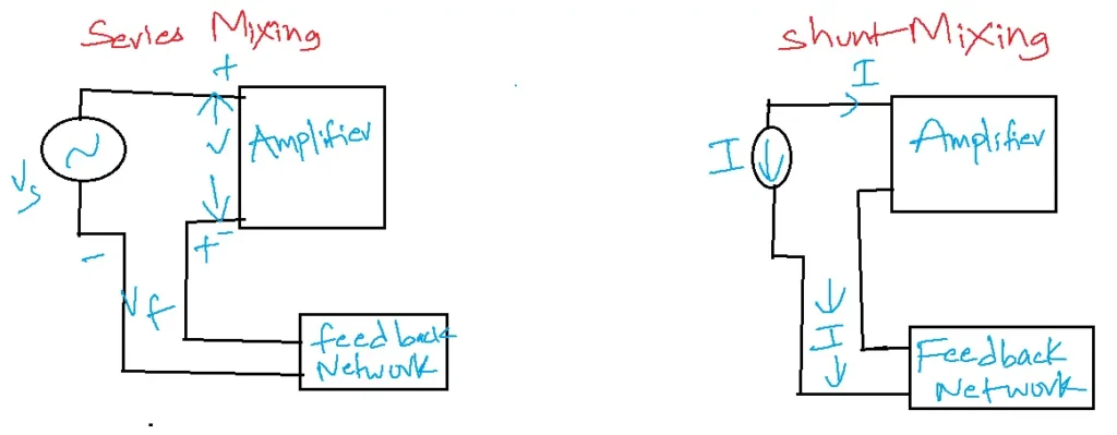
Mixer Network: Mixing Networks are of two types:
1. Series Mixing
2. Shunt Mixing
Series Mixing:
Vs = Vi + Vf
Vi = Vs – Vf
Shunt Mixing:
Is = Ii + If
There are four types of negative feedback amplifiers:
1. Voltage series
2. Current series
3. Voltage shunt
4. Current shunt
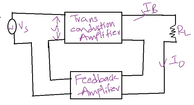
Voltage series feedback amplifier:
The configuration of this amplifier is shown in below figure:
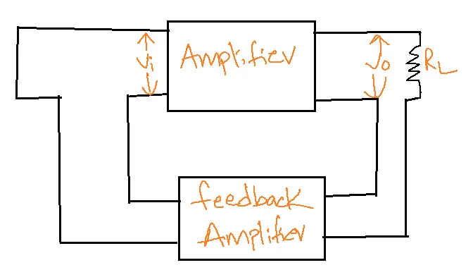
The simplified configuration of the voltage series is shown in the figure below:
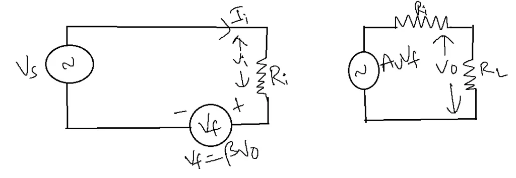
Input resistance RF = Ri(1+ Av β)
For voltage series , input resistance increases by the factor (1+ Av β)
To measure output resistance ROF makes
i. Vs = 0
ii. RL is excluded
iii. Apply external voltage V at the output.
ROF = RO(1+ Av β)
Current Series Feedback Amplifier:
Input resistance Rif :
Rif = Ri(1+ gmβ)
Output resistance (Rof):
Rof = Ro(1+ gmβ)
Voltage Shunt Feedback Amplifier:
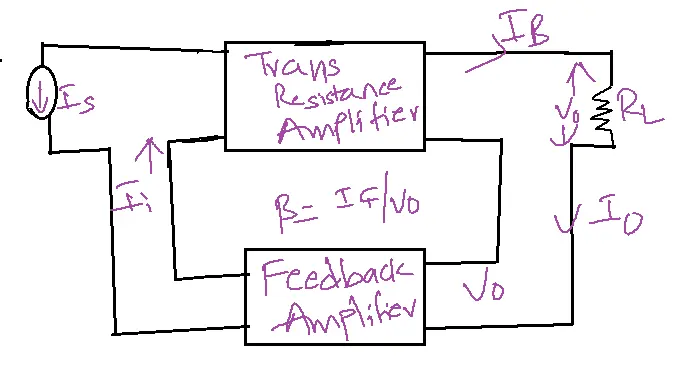
Input resistance Rif :
Rif = Ri(1+ Rmβ)
Rof = Ro(1+ Rmβ)
Current Shunt Feedback Amplifier:
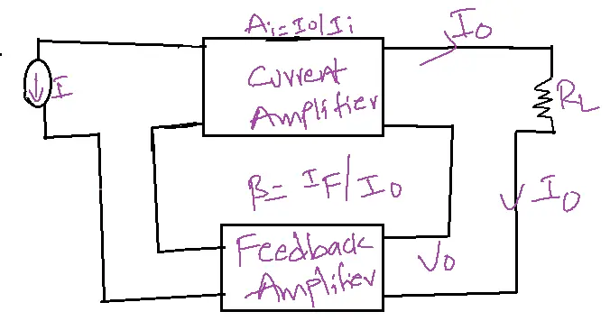
Input resistance Rif :
Rif = Ri(1+ Aiβ)
Output resistance (Rof):
Rof = Ro(1+ Aiβ)
| Types | Input resistance (Rif) | Output resistance (Rof) |
| Voltage series feedback amplifier | Increases | Decreases |
| Current series feedback amplifier | Increases | Increases |
| Voltage shunt feedback amplifier | Decreases | Decreases |
| Current shunt feedback amplifier | Decreases | Increases |
Methodology;
Due to any reasons, Ic may increase
Vc= IERE
Ic, IE → IERE →V0
From the circuit VB = VBE + V0
VBE decreases Ic decreases.
V0 = Vs
Feedback factor β = Vf/ V0 = 1.
The feedback element is RE.
Applications:
- Improved Amplifier Performance: Feedback amplifiers are essential for enhancing the performance of basic amplifiers. They can increase gain, reduce distortion, improve bandwidth, and stabilize the amplifier against temperature variations and component aging.
- Precision Instrumentation: Feedback amplifiers are crucial in precision instrumentation applications. They enable accurate amplification of weak signals from sensors and transducers, ensuring precise measurements in various scientific and industrial settings.
- Audio Systems: Feedback amplifiers play a significant role in audio systems, where they control volume, tone, and equalization. They also help reduce noise and distortion, contributing to high-quality sound reproduction.
- Control Systems: Feedback amplifiers are integral to control systems used in various applications, from industrial automation to robotics. They provide stable and predictable responses to control signals, ensuring precise control of processes and mechanisms.
- Oscillators: Feedback amplifiers can be configured to create oscillators, which generate periodic signals like sine waves, square waves, or triangle waves. These signals are used in various electronic devices, including clocks, communication systems, and test equipment.
FAQs of Feedback Amplifier:
1. What is a feedback amplifier?
- A feedback amplifier is an electronic amplifier that takes a portion of its output signal and feeds it back to the input.
- This feedback loop can be designed to improve various aspects of the amplifier’s performance, such as gain, bandwidth, distortion, and stability.
2. What are the different types of feedback amplifiers?
- The main types of feedback amplifiers are:
- Voltage-series feedback: The feedback signal is a voltage, and it is connected in series with the input signal.
- Current-series feedback: The feedback signal is a current, and it is connected in series with the input signal.
- Voltage-shunt feedback: The feedback signal is a voltage, and it is connected in parallel with the input signal.
- Current-shunt feedback: The feedback signal is a current, and it is connected in parallel with the input signal.
3. What are the advantages of using feedback in amplifiers?
- Feedback in amplifiers offers several benefits:
- Increased gain stability: This makes the amplifier’s gain less sensitive to variations in component values.
- Reduced distortion: Minimizes non-linear distortion in the output signal.
- Improved bandwidth: Widens the range of frequencies over which the amplifier operates effectively.
- Controlled input and output impedance: Allows for precise control of the amplifier’s input and output impedance.
- Reduced noise: Suppresses unwanted noise in the output signal.
4. What are the disadvantages of using feedback in amplifiers?
- The main disadvantages of feedback amplifiers are:
- Reduced gain: The feedback loop introduces a controlled reduction in gain, which is essential for achieving a more stable and predictable amplifier response.
- Potential for instability: If not designed carefully, feedback can cause the amplifier to oscillate or become unstable.
- Increased complexity: Feedback amplifiers can be more complex to design and analyze than non-feedback amplifiers.
5. What are the common applications of feedback amplifiers?
- Feedback amplifiers find applications in various fields:
- Audio systems: For volume control, tone control, and equalization.
- Instrumentation: For amplifying weak signals from sensors and transducers.
- Control systems: To deliver consistent and expected results in automated and robotic processes.
- Oscillators: Periodic signals used in clocks, communication systems, and test equipment.