
Digital Logic Design combinational circuits include the encoder and decoder. The Encoder and Decoder are essential components in digital logic design, serving opposite purposes in data processing and transmission.
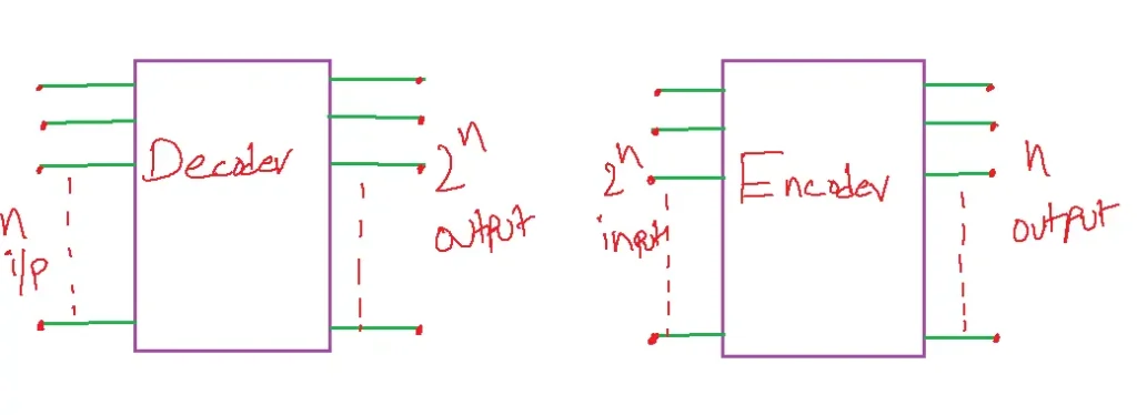
Table of Contents
DECODER
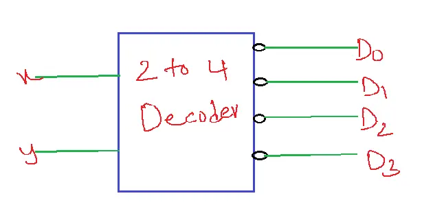
A decoder is a combination circuit that converts binary information from n input lines to a maximum of 2n unit output lines.
If the n-bit coded information has unused combinations, the decoder may have less than 2n output lines.
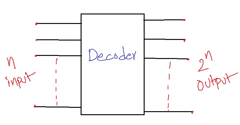
In general, the decoder is a combination circuit that transforms the binary information from n input lines to one of m output lines where m≤2n.
The purpose of the decoder is to generate 2n minimum terms.
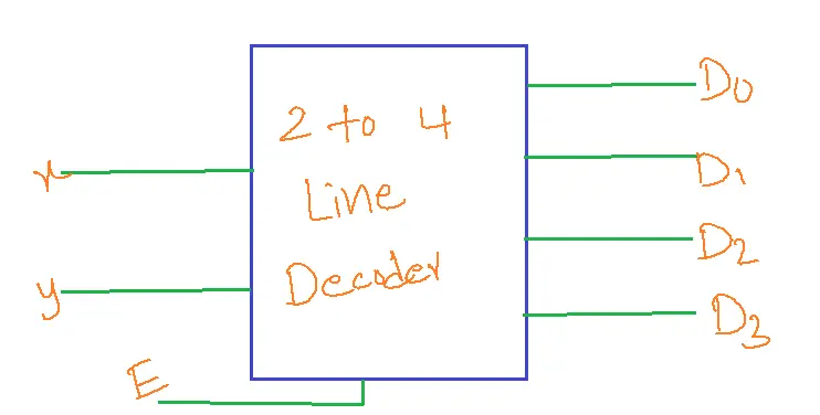
Function table
| x | y | D0 | D1 | D2 | D3 |
| 0 | 0 | 1 | 0 | 0 | 0 |
| 0 | 1 | 0 | 1 | 0 | 0 |
| 1 | 0 | 0 | 0 | 1 | 0 |
| 1 | 1 | 0 | 0 | 0 | 1 |
LOGIC DIAGRAM
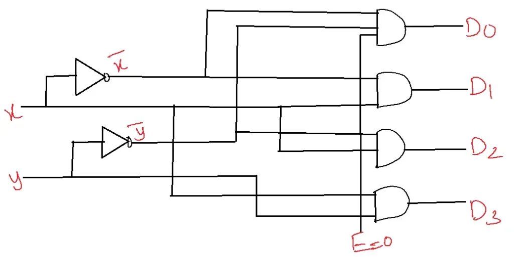
Regardless of input, all outputs D0 through D3 equal zero if allow input=0.
| E | x | y | D0 | D1 | D2 | D3 |
| 0 | X | X | 0 | 0 | 0 | 0 |
| 1 | 0 | 0 | 1 | 0 | 0 | 0 |
| 1 | 0 | 1 | 0 | 1 | 0 | 0 |
| 1 | 1 | 0 | 0 | 0 | 1 | 0 |
| 1 | 1 | 1 | 0 | 0 | 0 | 1 |
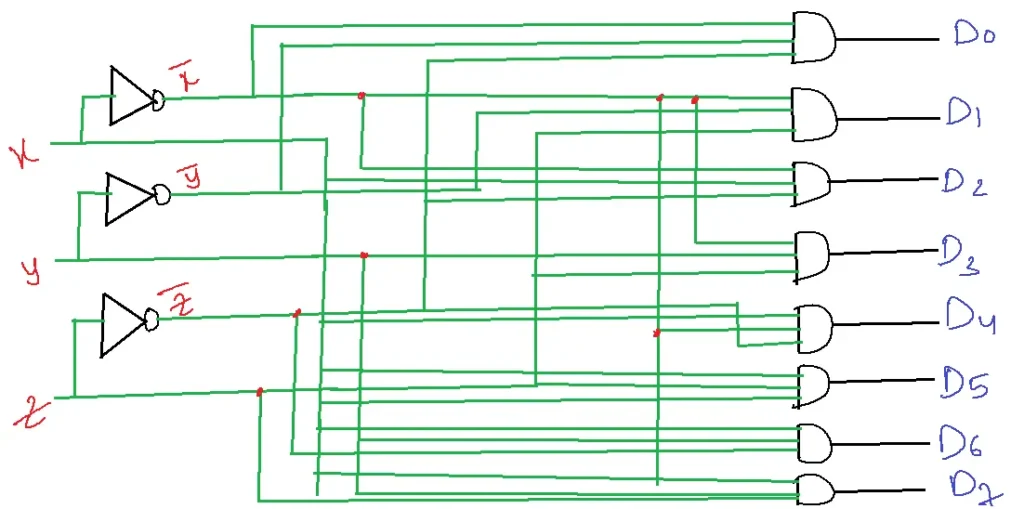
3 to 8-line Decoder
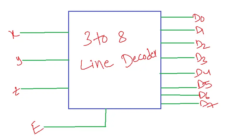
Function table:
| E | x | y | z | D0 | D1 | D2 | D3 | D4 | D5 | D6 | D7 |
| 0 | 0 | 0 | 0 | 0 | 0 | 0 | 0 | 0 | 0 | 0 | 0 |
| 1 | 0 | 0 | 0 | 1 | 0 | 0 | 0 | 0 | 0 | 0 | 0 |
| 1 | 0 | 0 | 1 | 0 | 1 | 0 | 0 | 0 | 0 | 0 | 0 |
| 1 | 0 | 1 | 0 | 0 | 0 | 1 | 0 | 0 | 0 | 0 | 0 |
| 1 | 0 | 1 | 1 | 0 | 0 | 0 | 1 | 0 | 0 | 0 | 0 |
| 1 | 1 | 0 | 0 | 0 | 0 | 0 | 0 | 1 | 0 | 0 | 0 |
| 1 | 1 | 0 | 1 | 0 | 0 | 0 | 0 | 0 | 1 | 0 | 0 |
| 1 | 1 | 1 | 0 | 0 | 0 | 0 | 0 | 0 | 0 | 1 | 0 |
| 1 | 1 | 1 | 1 | 0 | 0 | 0 | 0 | 0 | 0 | 0 | 1 |
LOGIC DIAGRAM
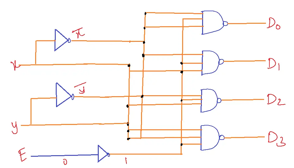
DECODER WITH NAND GATE
| E | x | y | D0 | D1 | D2 | D3 |
| 1 | X | X | 1 | 1 | 1 | 1 |
| 0 | 0 | 0 | 0 | 1 | 1 | 1 |
| 0 | 0 | 1 | 1 | 0 | 1 | 1 |
| 0 | 1 | 0 | 1 | 1 | 0 | 1 |
| 0 | 1 | 1 | 1 | 1 | 1 | 0 |
LOGIC DIAGRAM
Problems on decoder
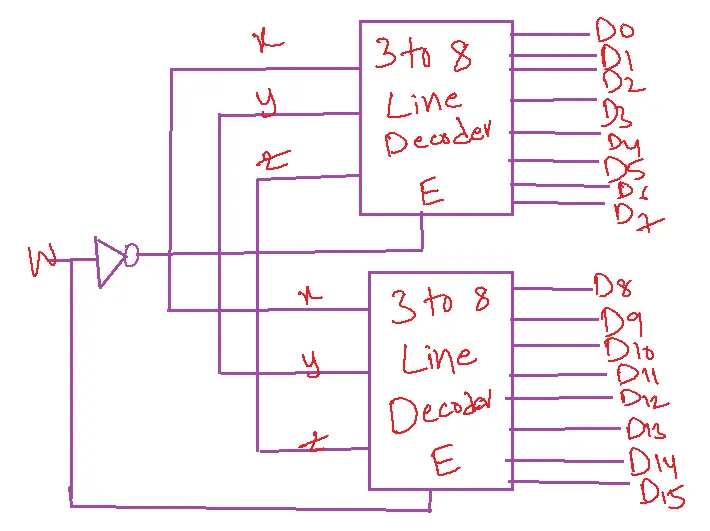
1. Design a 4 to 16-line decoder using a 3 to 8-line decoder
Solution:
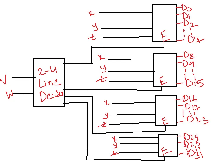
2. Construct a 5-32 line decoder with a 3-8 line decoder with enabling and one 2-4 line decoder.
Solution:
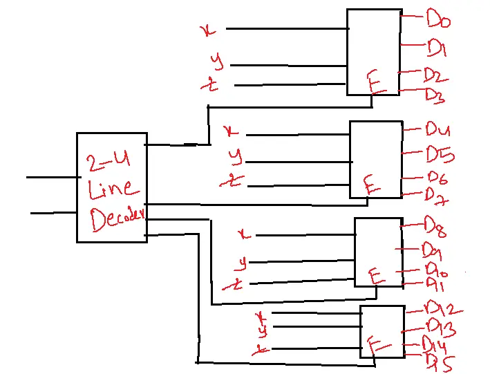
3. Construct a 4-16 line decoder with five 2-4 line decoders.
Solution:
Decoders can be used to realize any combination circuit.
1. To realize a combination circuit with n inputs, and m outputs the size of the decoder is n to 2n decoder and m OR gates.
2. If the decoder is constructed with AND gates, use OR gates as external gates.
3. If the decoder is constructed with NAND gates, use NAND gates as external gates.
Note: Before we realize any combinational circuit with a decoder, the Boolean function must be in the sum of min terms. Since it is generating 2n min terms.
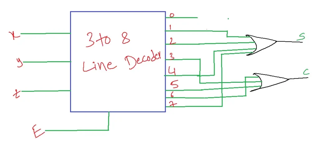
Realize a Full Adder using a decoder and external gates:
1. Full adder is a combinational circuit with 3 inputs x,y, and z with 2 outputs S, C.
2. n to 2n decoder n=3,m=2 3 to 8 is decoder required.
3. Since m=2 two OR gates are required.
FULL ADDER Truth table
| x | y | z | S | C |
| 0 | 0 | 0 | 0 | 0 |
| 0 | 0 | 1 | 1 | 0 |
| 0 | 1 | 0 | 1 | 0 |
| 0 | 1 | 1 | 0 | 1 |
| 1 | 0 | 0 | 1 | 0 |
| 1 | 0 | 1 | 0 | 1 |
| 1 | 1 | 0 | 0 | 1 |
| 1 | 1 | 1 | 1 | 1 |
S(x,y,z)=∑m(1,2,4,7)
C(x,y,z)=∑m(3,5,6,7)
1. A function with a long list of min terms requires an OR gate with more inputs.
2. A function having a list of K-min terms can be expressed in its complement form F’ with 2n-K min terms.
3. Fuel terms can be applied to represent the function if there are more min terms than 2n/K.
4. It is useful to sum the minimum terms of F’ in these situations, using the NOR gate. The output of the NOR gate complements the sum and generates normal output F.
Applications of Decoder
Decoder circuits have numerous applications in digital logic design, including:
1. Memory Address Decoding: Decodes memory addresses to select specific memory locations.
2. Display Drivers: Drives display devices like LEDs, LCDs, or 7-segment displays.
3. Data Demultiplexing: Routes data from a single input to multiple outputs.
4. Instruction Decoding: Decodes instructions in microprocessors and microcontrollers.
5. Error Detection and Correction: Detects and corrects errors in digital data.
6. Digital Multiplexing: Selects one of many input signals and forwards it to a single output.
7. Alarm and Security Systems: Decodes sensor inputs to trigger alarms or security measures.
8. Digital Communication Systems: Decodes received data in communication systems like modems or network interfaces.
9. Computer Input/Output (I/O) Operations: Decodes I/O instructions and addresses.
10. Embedded Systems: Decodes inputs and controls outputs in embedded systems like traffic lights or robots.
ENCODER
An encoder is a combination circuit that performs the inverse operation of the decoder.
2n to n
2n-input n-output
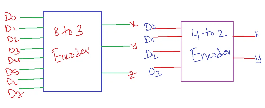
The truth table for 4 to 2 Encoder:
| D0 | D1 | D2 | D3 | x | y |
| 1 | 0 | 0 | 0 | 0 | 0 |
| 0 | 1 | 0 | 0 | 0 | 1 |
| 0 | 0 | 1 | 0 | 1 | 0 |
| 0 | 0 | 0 | 1 | 1 | 1 |
x=D2+D3
y= D1+D3
Only one input must be high at any time.
The output is (0,0) even if all inputs are 0’s.
Encoder circuits are essential in digital logic design, enabling efficient data processing, transmission, and storage in various digital systems.
Types of encoders
– Binary Encoder
– Decimal Encoder
– Gray Code Encoder
– Priority Encoder
– 8b/10b Encoder (for data transmission)
Applications
1. Data Compression: Encodes data to reduce its size for efficient storage or transmission.
2. Error Detection and Correction: Encodes data with error-checking bits for reliable transmission.
3. Digital Communication Systems: Encodes data for transmission over communication channels.
4. Computer Networks: Encodes data for routing and addressing in computer networks.
5. Cryptography: Encodes data for secure transmission and storage.
6. Digital Signal Processing: Encodes audio, image, or video signals for processing and transmission.
7. Keyboard and Keypad Encoding: Encodes keystrokes for computer input.
8. Priority Encoding: Encodes priority levels for scheduling and interrupt handling.
9. Binary Coded Decimal (BCD) Encoding: Encodes decimal numbers for arithmetic and display purposes.
10. Digital Control Systems: Encodes control signals for industrial automation and control systems.
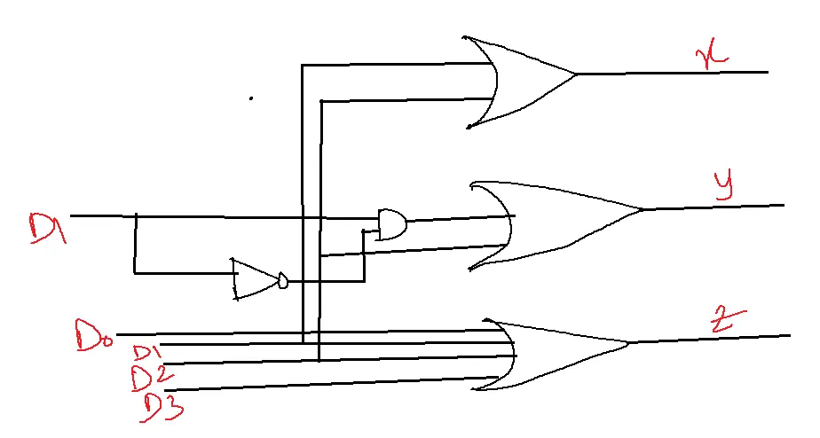
Priority Encoder
A priority encoder is an encoder that includes a priority function. The operation of this priority encoder is such that if two or more inputs are equal to one at the same time the input having the highest priority will take precedence.
In addition to the outputs x and y circuits have a third output designated by V(valid). This is a valid bit indicator i.e., set to 1 when one or more inputs are equal to one. If all the inputs are 0, there is no valid input, and V=0. The other two outputs are inspected at V=1.
The other two outputs are not inspected when V=0 and are specified as don’t care conditions.
Example: Design a priority encoder by giving D3 the highest priority and the third output V.
Sol: Truth table of Priority Encoder
| D0 | D1 | D2 | D3 | x | y | V |
| 0 | 0 | 0 | 0 | X | X | 0 |
| 1 | 0 | 0 | 0 | 0 | 0 | 1 |
| X | 1 | 0 | 0 | 0 | 1 | 1 |
| X | X | 1 | 0 | 1 | 0 | 1 |
| X | X | X | 1 | 1 | 1 | 1 |
4-Variable K-Map:
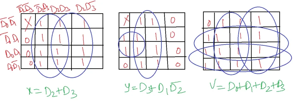
x=D2+D3
y=D3+D1D2’
V=D0+D1+D2+D3
Key differences between Encoder and Decoder
– Direction of data flow in encoder and decoder: Encoder (many-to-one), Decoder (one-to-many)
– Purpose of encoder and decoder: Encoder (compression, encoding), Decoder (expansion, decoding)
– Output of encoder and decoder: Encoder (single code), Decoder (multiple outputs)
Similarities between Encoder and Decoder
– Both encoder and decoder use digital logic gates (AND, OR, NOT) and combinational logic
– Both the encoder and decoder have multiple inputs and outputs
– Both the encoder and decoder are used in digital communication systems and computer networks
– Both Encoder and Decoder produce outputs instantly, without any delay.
– Encoder and Decoder are used in digital communication systems, computer networks, and digital electronics.
-Both Encoder and Decoder can be designed and analyzed using truth tables.
-Both the Encoder and Decoder are used for error detection and correction.
– Both the Encoder and Decoder are involved in data processing, either compressing or expanding data.
FAQs
1. What is an encoder in digital logic design?
- An encoder is a combinational logic circuit that translates multiple input lines into a binary code output, indicating the active input.
- It essentially “encodes” information from a larger set of inputs into a more compact form.
2. What is a decoder in digital logic design?
- A decoder is a combinational logic circuit that performs the reverse operation of an encoder.
- It takes a binary code as input and activates one of its multiple output lines corresponding to the input code.
- Essentially, it converts the encoded information back into its original format.
3. What are the main differences between encoder and decoder?
- Function of Encoder and Decoder: Encoders function by encoding multiple input signals into a binary representation, while decoders decode this binary representation back into the original multiple output signals.
- The number of inputs and outputs of Encoder and Decoder: Encoders typically have more inputs than outputs, while decoders have more outputs than inputs.
- The direction of information flow in Encoder and Decoder: Information flows from multiple inputs to a single output in an encoder, while it flows from a single input to multiple outputs in a decoder.
4. What are some common applications of encoders?
- Keypad encoding: Encoders are used in keypads to convert key presses into corresponding binary codes for processing by a microcontroller.
- Priority encoding: Priority encoders identify the highest priority active input and generate its corresponding binary code.
- Data compression: Encoders optimize data representation, achieving a more compact form for efficient storage and transmission.
5. What are some common applications of decoders?
- Memory address decoding: Decoders select specific memory locations based on the binary address provided.
- Seven-segment displays: Decoders convert binary codes into signals that drive seven-segment displays to show numbers or characters.
- Data demultiplexing: Decoders can route a single input signal to one of several output lines based on a select code.
6. What is a priority encoder?
- A priority encoder is a digital circuit that converts multiple input lines into a binary code, giving precedence to the active input with the highest priority.
- This makes it useful in scenarios where multiple inputs might be active simultaneously.
7. How does a priority encoder differ from a regular encoder?
- A regular encoder converts its active input into a binary code, without considering priority.
- In contrast, a priority encoder prioritizes the highest-priority active input, providing its binary code regardless of other active inputs.
8. What are the applications of a priority encoder?
- Priority encoders are commonly used in:
- Interrupt handling: Determining which device triggered an interrupt in a microprocessor or microcontroller system.
- Keyboard encoding: Identifying which key was pressed on a keyboard, even if multiple keys are pressed simultaneously.
- Error detection and correction: Identifying the location of the first error in a data stream.
9. How is a priority encoder implemented?
- Priority encoders can be implemented using various digital logic components, such as:
- Logic gates (AND, OR, NOT)
- Multiplexers
- Programmable logic devices (PLDs)
10. What are some common challenges in designing with priority encoders?
- Priority assignment: Determining the priority levels of the input lines based on the application requirements.
- Minimization of logic gates: Designing the priority encoder circuit to use the minimum number of gates for efficiency.
- Timing considerations: Ensuring the priority encoder operates correctly at the desired clock frequency.