
- A directional coupler is a tool used in measurements to take a tiny sample of microwave power. The power measurements comprise VSWR values, incident, and reflected power, among other things.
- It is a 4-port wave guide junction, consisting of a primary main wave guide and a secondary auxiliary wave guide. The illustration of a directional coupler is shown in the accompanying figure.
- It is used to pair either bi-directional or unidirectional microwave power.
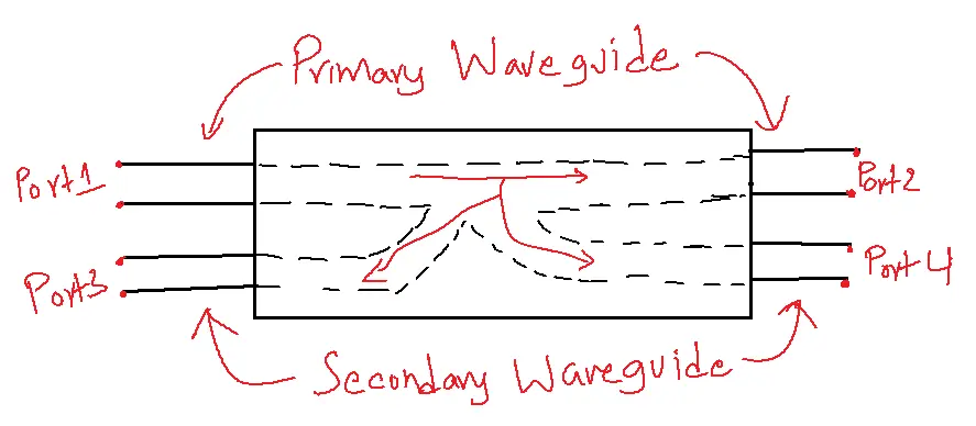
Table of Contents
Properties of Directional Coupler:
An ideal directional coupler has the following characteristics.
- Every termination has a matching port.
- A portion of the power that flows from Port 1 to Port 2 is linked to Port 4, not Port 3.
- The bi-directional nature of the connection allows some electricity flowing from Port 2 to Port 1 to be coupled with Port 3, but not with Port 4.
- A portion of the power linked to Port 2 but not Port 1 is incident through Port 3.
- A portion of the electricity linked to Port 1 but not Port 2 is incident through Port 4.
- Although the output of Port 3 should ideally be zero, in practice, a tiny amount of power known as back power is recorded at Port 3.
- The power flow in this coupler is depicted in the accompanying figure. Ports 1 and 3 are decoupled, as are Ports 2 and 4.
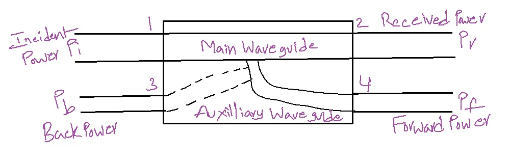
Where Pi= Incident power at Port 1
Pr= Received power at Port 2
Pf= Forward coupled power at Port 4
Pb = Back power at Port 3
The parameters that determine a directional coupler’s performance are listed below.
- Coupling Factor (C) – A directional coupler’s coupling factor, expressed in dB, is the ratio of incident power to forward power.
C = 10log10Pi / PfdB - Directivity (D)— Directivity expressed in dB, is the product of its forward and backward powers.
D=10log10Pf/PbdB - Isolation (I)— It outlines a directional coupler’s directing characteristics. It represents the ratio of incident power to reflected power, expressed in decibels (dB).
I = 10log10Pi / PbdB
Directivity + Coupling factor = Isolation in dB
Two-Hole Directional Coupler:
This directional coupler features a pair of small apertures common to both the primary and secondary wave guides. The spacing between these holes is λg/4, where λg represents the guiding wavelength. A two-hole directional coupler’s picture can be seen in the accompanying figure.
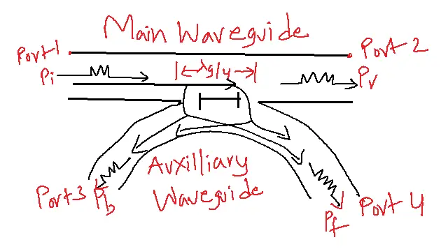
The ideal purpose of a directional coupler is to prevent back power, and a two-hole directional coupler is made to fulfill this need. Through holes 1 and 2, some of the power traveling between Ports 1 and 2 escapes.
The size of the holes determines the power’s magnitude. Leakage power from both holes is in phase at hole 2, adding to the total energy that goes toward the forward power Pf. It is out of phase at hole 1, though, canceling each other and keeping the back power from happening.
As a result, a directed coupler’s directivity increases.
Applications of Directional Coupler:
- Power Measurement and Monitoring: It measures microwave power levels, ensuring optimal system performance and preventing damage.
- Signal Sampling and Injection: By tapping into a signal with minimal disruption, directional couplers enable essential tasks like spectrum analysis, monitoring, and fault detection.
- Antenna Systems and Duplexers: In antenna systems, directional couplers facilitate the isolation of transmitted and received signals, preventing interference and improving overall system performance. They are also key components in duplexers, allowing simultaneous transmission and reception on a single antenna.
- Feedback and Control Loops: These are used in feedback and control loops to provide a sample of the output signal for comparison with the desired signal. This enables precise control and regulation of various parameters within a microwave system.
- Reflectometry and VSWR Measurement: These facilitate reflectometry techniques by enabling the measurement of reflected power and VSWR, crucial parameters for evaluating transmission lines and microwave components.
Applications of Two-Hole Directional Coupler:
1. Signal Monitoring: Sampling signals for measurement, testing, or monitoring without interrupting the main transmission.
2. Power Measurement: Measuring signal power levels in microwave systems.
3. Frequency Measurement: Measuring signal frequencies in microwave systems.
4. Signal Injection: Injecting a test signal into a transmission line for testing purposes.
5. Antenna Beamforming: Used in phased array antennas to control and monitor signal distribution.
6. Radar Systems: Used in radar systems for signal processing and monitoring.
FAQs of Related topic:
1. What is a Directional Coupler?
- A directional coupler is a passive device that samples a portion of the microwave signal traveling in one direction on a transmission line, while minimally affecting the main signal path.
- This makes it invaluable for various measurement and control applications.
2. What are the main types of Directional Couplers?
- There are several types, including:
- Two-hole couplers: Simple and widely used, based on coupling through two small holes in the waveguide walls.
- Bethe-hole couplers: Offer higher directivity and broader bandwidth compared to two-hole couplers.
- Branch-line couplers: Compact and easy to fabricate, often used in planar circuits.
- Hybrid couplers: Equally distribute power and ensure isolation among output ports, making them well-suited for balanced circuit applications.
3. What are the key parameters of a Directional Coupler?
- Coupling factor: The ratio of power at the coupled port to the input power, expressed in dB.
- Directivity: The forward-to-reverse power coupling ratio quantifies the degree of isolation between ports.
- Insertion loss: The power loss introduced by the coupler in the main transmission path.
- Frequency range: The range of frequencies over which the coupler operates effectively.
4. What are the applications of Directional Couplers in Microwave Engineering?
- Power measurement and monitoring: Accurately measure incident, reflected, and transmitted power levels.
- Signal sampling and injection: Extract a portion of the signal for analysis or introduce a test signal without disrupting the main path.
- Antenna systems and duplexers: Isolate transmitted and received signals, and enable simultaneous transmission and reception.
- Feedback and control loops: Provide a sample of the output signal for comparison and control.
- Reflectometry and VSWR measurement: Help measure reflected power and characterize transmission lines.
5. How do I choose the right Directional Coupler for my application?
- Consider the following factors:
- Frequency range: Ensure the coupler operates within the desired frequency band.
- Coupling factor: Choose the appropriate coupling value for the desired signal sampling or power division.
- Directivity: Select a coupler with sufficient directivity to minimize unwanted signal coupling.
- Power handling: Ensure the coupler can handle the maximum power levels expected in the system.
- Package and connector type: Choose a coupler compatible with your system’s mechanical and electrical requirements.