
- A DC machine can act as a DC generator as well as a DC motor.
- If input to the machine is mechanical energy and produces electrical energy, it is said to be a DC Generator.
- Electrical energy is measured in terms of voltage and current.
- Electrical Power Pe = VI V- Amp or watts
- Mechanical energy is measured in terms of speed and torque.
- PM=w x T
- Where w is angular speed measured in radians/sec.
- Speed can also be measured by N. N is a rotational speed measured in rpm.
- The relation between w and N can be given as
- w=2πN/60
- Pm = w.T=2πNT/60
Table of Contents
Electrical machines are classified into 3 types:
1. AC Machine
2. DC Machine
3. Special Machine
AC Machine classified into 2 types:
1. AC Generators
2. AC Motors
AC Generators are classified into 2 types:
1. Synchronous generators
2. Asynchronous generators (Induction generators)
AC Motors are classified into 2 types:
1. Synchronous Motors
2. Asynchronous Motors (Induction Motors)
DC Machine classified into 2 types:
1. DC Motor
2. DC Generator
Special Machine classified into 2 types:
1. Special Motor
2. Special Generator
Principle of DC Generator:
A DC Generator converts mechanical energy into electrical energy based on the principle of Faraday’s law of electromagnetic induction and operates by “Dynamically induced emf”. [having stationary magnetic flux concerning time and rotating/moving conductor].
Faraday’s Law of Electromagnetic Induction:
Whenever the conductor cuts, magnetic-induced emf is produced.
To satisfy dynamically induced EMF DC machine is constructed mainly with two parts. They are stators, meaning they remain stationary within the machine.
The rotor is the rotational plot.
To satisfy dynamically induced EMF conductor is placed on a rotor and flux will be produced on the stator in a DC Machine.
Construction of a DC Machine:
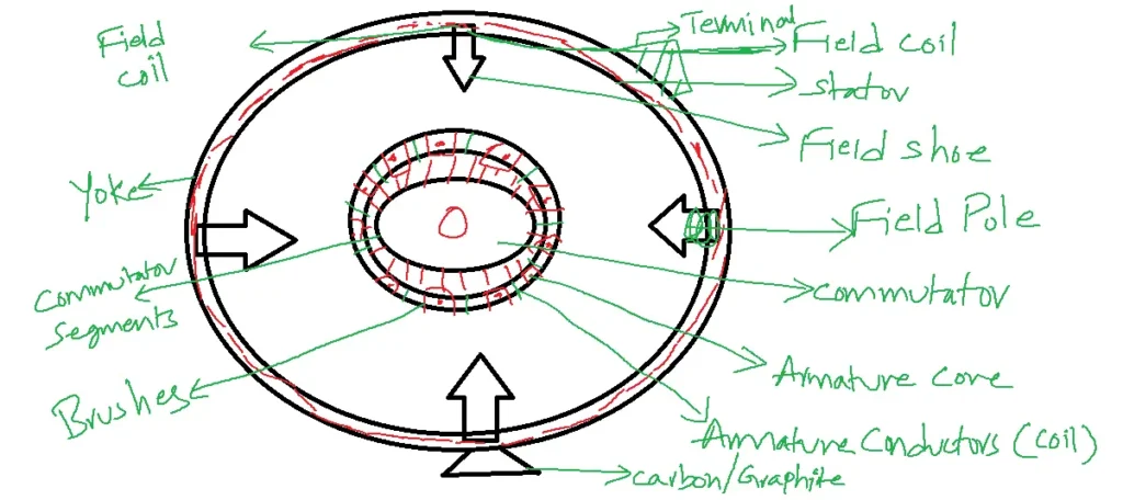
A DC Generator converts mechanical energy to electrical energy possessing construction features as follows.
With the same constructional features of electrical energy converted into mechanical energy, it is nothing but a DC Motor. So the same construction features are also said to the DC motor. So this construction features are known as a DC machine.
The main parts of the DC Machine:
1. Yoke – It is made of cast iron or steam. It provides a mechanical strength to a machine. It is a return path for magnetic flux.
2. Field coil, field pole, or field shoe.
3. Armature core or Armature conductors.
4. Commutator brushes.
Armature is a group of conductors that are arranged in slots. These conductors are arranged in slots with two types of connections:
1. Wave winding
2. Lap winding
In wave winding, the number of parallel paths N = 2.
In lap winding, the number of parallel paths N=P, where P is the number of field poles of a machine.
Commutator:
This mechanical or rotating device rectifies the induced AC voltage, transforming it into a pulsating unidirectional voltage. Each commutator segment is connected to each armature conductor.
Commutator Brushes: These stationary brushes maintain contact with the commutator segments, collecting the voltage induced in the conductors.
Principle of DC Generator or operation of single loop coil/single turn coil:
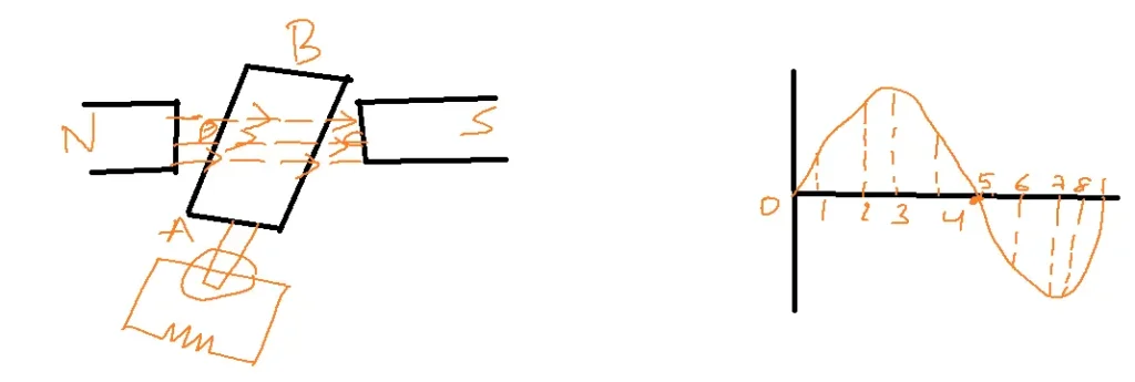
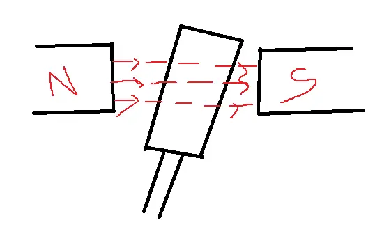
Consider a single-turn coil rotating in a magnetic flux as shown in the figure.
When a conductor is at position 1 which is perpendicular to magnetic flux.
The number of flux linkages with the conductor is maximum. When a conductor is moved from position 1 to 2 change in flux linkages will be minimum. So EMF induced in a conductor is minimal.
When the conductor moves from position 2 to 3 alter in flux linkage increases compared to position 1 to 2. So emf induced in the conductor at position 3 is maximum.
Therefore when the conductor is placed parallel to magnetic flux lines position emf induced will be maximum. Similarly, the change in flux linkages from position 3 to 4 is minimal and less than the previous position, and further rotation will decrease the change in flux linkages. So emf induced decreases in proportion.
During rotation from position 1 to 5, current flows from coil sides AB to CD. Then, from position 5 to 8, Fleming’s right-hand rule dictates that the current reverses direction.
Therefore emf produced in a conductor will be in the reverse direction as shown in the figure below:
Note: According to Faraday’s law of electromagnetic induction emf is equal to
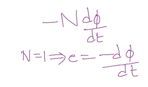
The ‘-‘ Sign indicates lens law
N – number of coil turns
In the given case N=1,
Therefore emf produced in a conductor is directly proportional to change in flux linkages.
EMF equation of DC Generator:
- The generated emf in the DC generator can derived as follows:
- Phi=flux per pole in Weber
- P = number of poles in the DC machine
- N = Number of revolutions of an armature per minute.
- Z = total number of armature conductors.
- A = number of armature parallel paths.
- According to Faraday’s law
- Flux current vy each conductor for one complete rotation = P time taken to complete 1 revolution by armature
- N – 60 sec
- 1 -t
- Nt=60 t=60/N sec
- Image
- emf per each parallel path or emf across an armature terminals
- A indicates several parallel paths of an armature winding. This type of winding is used for high voltage and low current applications.
Classification of DC Generator:
There are two primary types of DC generators: separately excited and self-excited.
Self-excited DC generator is again classified into 3 types.
1. DC series generator
2. DC shunt generator
3. DC compound generator
DC compound generator consists of long shunt and short shunt compound generator.
Example:
A six-pole machine has an armature of 90 slots and 8 conductors per slot running at 1000 rpm. The flux per pole is 0.05wb. Calculate the induced emf for a wave-connected configuration. Also, determine emf by considering 144 slots with two coil sides per slot each coil having 2 turns.
Solution:
P=6
Z=90 slots
0.05wb
N =1000 rpm
Number of conductors = number of slots x number of coil sides per slot x number of turns per coil
Case-i: z=90 x 8 =720
Eg= zN/60 x P/A
A=2
Eg= 1800 V.
Case-ii: z = 144 x 2 x 2
Z = 576.
Eg= 1440 V.
Losses in DC Generator:
Calculating the efficiency of a generator requires knowledge of the machine’s losses.
Efficiency of a generator ng = output/output + losses[input]
= electrical output/ electrical output + iron loss + copper loss + mechanical loss.
Mechanical losses are lowest compared to iron losses and copper losses.
Therefore ng = electrical output/ electrical output + iron loss + copper loss
Power flow in a DC generator:
Mechanical efficiency of a generator nm = B/A.
Electrical efficiency of a generator ne=C/B
Commercial efficiency nc = C/A also called overall efficiency.
nc = nm x ne
unless it is specifically asked always determine overall or commercial efficiency.
Types of Losses:
There are 3 types of losses in a DC generator:
Magnetic Losses or Iron Losses or Core Losses
Two types of Iron losses. They are
Hysteresis Losses(wH): The reversal of magnetization in the core, known as hysteresis, results in energy losses called hysteresis losses (wH).
WH=nBmax1.6fV watts
n is the Steimatz coefficient. It depends on the type of material. For hard stream n=502 J/m3 silicon steam n= 191 J/m3. Generally, silicon steam is preferred.
B = magnetic flux density
f = frequency of armature core
V= volume of core
Eddy current losses: EMF induced in the conductor. This emf also passes through the armature core. This current generates heat in a core known as eddy current losses. These can be reduced by dividing the core into a small thin lamination.
WE=KB2maxf2t2V watts
t = thickness of laminations.
Mechanical Losses:
There are two types:
1. Friction
2. Windage
Friction losses occur due to wirings and brushes.
Windage losses occur due to the overcoming of wind forces.
Copper losses:
1. Armature copper loss
2. Field copper loss
Copper losses are a significant factor in determining efficiency, typically accounting for 30-40% of total losses in a machine.
Characteristics of a DC Generator:
There are 3 types of characteristics for a DC generator to be plotted to understand the performance of the DC generator based on field winding connections and load variations.
1. The open-circuit characteristic curve, also known as the magnetization characteristic, illustrates the relationship between open-circuited electromotive force (EMF) and field current.
2. External characteristics: The external characteristic curve plots the relationship between generated electromotive force (EMF) and armature current.
3. Internal characteristics: The internal curve is between load voltage versus armature current.
Related FAQs
Q1: What is the basic operating principle of a DC generator?
- A DC generator converts mechanical energy into electrical energy through electromagnetic induction.
- When a conductor (armature) rotates within a magnetic field, an electromotive force (EMF) is induced in it.
- This EMF causes a current to flow when the circuit shuts, generating DC power.
Q2: Explain the role of the commutator in a DC generator.
- The commutator is a vital component in a DC generator.
- It acts as a mechanical rectifier, converting the alternating current (AC) induced in the armature into direct current (DC) at the output terminals.
- It consists of segmented copper bars insulated from each other, and it works in conjunction with brushes to ensure a unidirectional current flow.
Q3: What are the different types of DC generators, and how do they differ regarding field winding connections?
The main types are:
- Separately Excited: Field winding is supplied from a separate DC source.
- Shunt: Field winding is connected in parallel with the armature.
- Series: Field winding is connected in series with the armature.
- Compound: Combination of shunt and series field windings.
These configurations affect the generator’s output voltage characteristics and suitability for applications.
Q4: How can we analyze the performance of a DC generator using equivalent circuit models?
- Equivalent circuit models represent the DC generator’s internal components as resistances and voltage sources.
- By applying network analysis techniques (KVL, KCL, etc.) to these models, we can calculate parameters like armature current, terminal voltage, efficiency, and voltage regulation under varying load conditions.
Q5: What are the typical applications of DC generators in modern electrical systems?
While AC generators are more common, DC generators still find applications in:
- Battery charging: Providing a constant DC voltage for charging batteries.
- Electroplating: Supplying a controlled DC for depositing metals.
- DC motors: Acting as a power source for DC motors in specific applications.
- Excitation systems: Providing field current for larger AC generators in power plants.