
Signal: A single-valued function of time, space, or any other independent parameter.
System: The purpose of the system is to extract useful information from the signal. It is defined as a group of physical components arranged in such a way that it gives proper output.
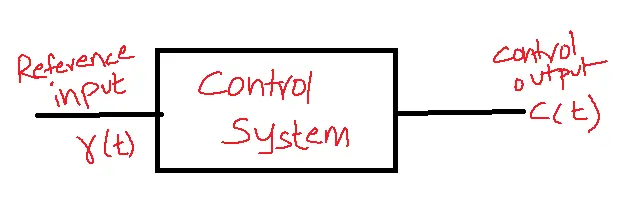
Control System: A control system is a group of physical components arranged in such a way that it passes the desired output using control or regulation either direct or indirect methods.
Table of Contents
General Representation:
Classification of Control Systems:
There are two types of control systems:
1. Open loop
2. Closed loop
Open loop control system:
- Open loop control systems lack feedback mechanisms, meaning the output has no impact on the system and its regulation cannot be monitored.
Transfer Function:
- It is defined as the ratio of the Laplace transform of output c(t) to the Laplace transform of input r(t).
TF=L[c(t)]/L[r(t)] = L[output]/L[input] = c(s)/r(s)|initial conditions=0.
Closed loop control system:
- In a closed-loop control system feedback is taken from the output of a system to monitor whether the outcome is controlled.
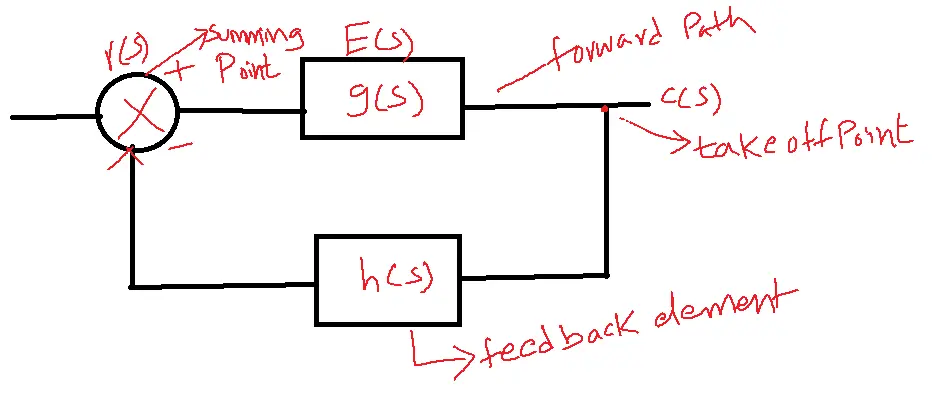
E(s) is the error signal, g(s) represents forward path gain, and h(s) represents the feedback element. The feedback element could be positive or negative.
Mathematical Models of a Control System:
The mathematical model consists of a set of differential equations. The control system’s response is determined by finding the solution to the differential equations.
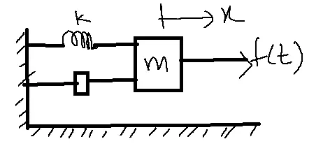
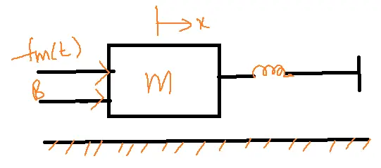
Mechanical Translation System:
The basic elements of a mechanical translation system are mass(M), friction(B), and spring constant(K).
The weight of the object is represented by mass. The elastic nature of an object is represented by spring. The friction in the mechanical system can be represented by dash part B.
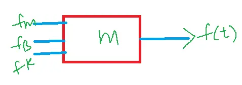
A force is applied on a mechanical system it is opposed by opposing forces due to mass, friction, and spring constant.
From Newton’s second law, the sum of forces acting on the object is equal to zero which means the applied force is equal to the sum of opposing forces due to m, B, K.
List of symbols used:
x – Displacement
V – velocity dx/dt
a – acceleration d2x/dt2
f – applied force
fm – opposing force due to mass
fB – opposing force due to friction
fK – opposing force due to spring constant
m – mass
B – friction
K – spring constant
Force Balancing Equations:
1. Mass :
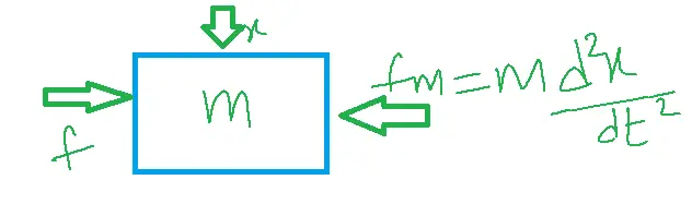
from Newton’s second law
f=fm=ma=m d2x/dt2
=mdV/dt
2. Friction or Dash part(B):
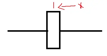
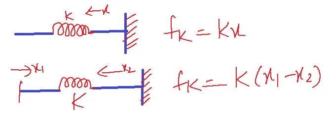
fB=Bdx/dt=BV
The opposing force due to friction, f=fB=B(dx/dt)=BV
When the dash part is placed between two objects concerning the first object then the opposing force due to the dash part is fB=Bd/dt(x2-x1)
3. Spring constant(K):
Problems Related to the topic:
1. Write the differential equation of a given mechanical translation system and determine the transfer function of the system.
input f(t)– F(s)
output x(t)–x(s)
f(t)=fm+fB+fK
=m d2x/dt2+Bdx/dt+Kx
Apply inverse Laplace transform
F(s)=ms2x(s)+Bs(x(s))+Kx(s)
=x(s)[ms2+Bs+K)
x(s)/F(s)=1/ms2+Bs+K
ANALOGOUS SYSTEMS:
Analogous systems are of two types:
1. Force-voltage analogy
2. Force-current analogy
Force-Voltage Analogy:
Consider a mechanical translation system with m, B, and K.
So f(t)= m d2x/dt2+Bdx/dt+Kx
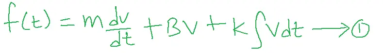
dx/dt=V
consider series RLC circuit
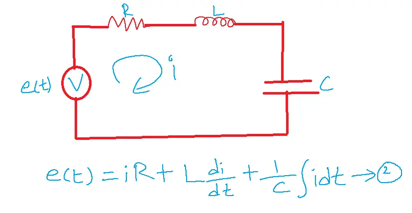
by comparing 1 and 2 the analogous parameters are:
| Mechanical Ts | Electrical system |
| Force f(t) | Voltage-e(t) |
| Friction-B | Resistor-R |
| Mass-m | Inductor-L |
| Spring-K | Capacitor-1/C |
| Velocity-v | Current-i |
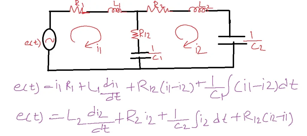
Problem: Write the Differential equation of the given mechanical translation system and convert it into an equivalent electrical system using force voltage analogy.
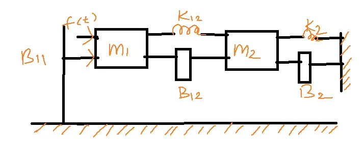
Solution:
Free body diagram of m1
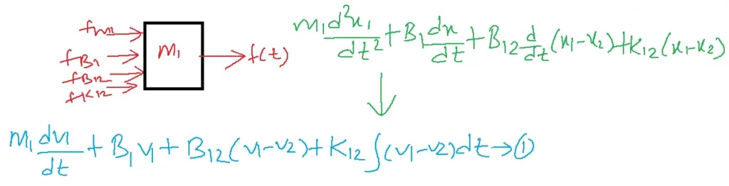
For m2
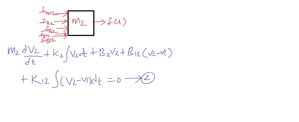
From 1 into electrical form
f(t)–e(t)
m1–L1
B1–R1
B12–R12
K12–1/C12
M2–L2
K2–1/C2
B2–R2
B12–R12
K12–1/C12
B12 and K12 are common in 1 and 2.
Force-Current Analogy:
Consider parallel RLC circuit
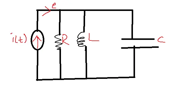
Current developed across
R=e/R
L=1/L integral of edt.
C=C de/dt
| Force | current |
| f(t) | i(t) |
| B | R |
| m | C |
| K | 1/L |
| V(t) | e(t) |
Convert the problem into an equivalent electric circuit using a force-current analogy.
f(t)-i(t) m1-C1
m2-C2 B1-1/R1
B2-1/R2 K1-1/L1
K2-1/L2 B2-1/R2
K2-1/L2
B2 and K2 are common parameters.
i(t)=C2de2/dt+1/R2(e2-e1)+1/L2 integral of (e1-e2)dt
0=e1/R1+1/L1 integral of e1 dt +c1 de1/dt+1/R2(e1-e2)dt+1/L2 integral of (e1-e2)dt
FAQs related to the topic
Q1. What is a control system, and what are its main components?
- A control system manages, commands, directs, or regulates the behavior of other devices or systems.
- Its main components include a plant (system to be controlled), sensors, actuators, and a controller.
Q2. What are the different types of control systems?
- The classification of control systems depends on multiple factors, including the presence or absence of feedback (open-loop vs. closed-loop), the nature of the system’s behavior (linear vs. non-linear), the constancy of system parameters over time (time-invariant vs. time-variant), and the nature of the signals being processed (continuous-time vs. discrete-time).
Q3. What are the essential concepts in control system analysis and design?
- Key concepts include transfer functions, block diagrams, stability analysis (using techniques like Routh-Hurwitz criterion and root locus), frequency response analysis (Bode plots and Nyquist plots), and controller design (PID control, lead-lag compensators).
Q4. How are control systems used in real-world applications?
- Control systems are pervasive in various industries, including robotics, aerospace, automotive, manufacturing, power systems, and household appliances like thermostats and washing machines.
Q5. What are the challenges and future trends in control system engineering?
- Challenges include designing robust controllers for complex systems, dealing with uncertainties and disturbances, and incorporating artificial intelligence and machine learning techniques.
- Future trends involve developing adaptive and intelligent control systems for autonomous vehicles, smart grids, and other emerging technologies.