
The attenuator is employed to lessen the signal amplitude without changing the waveform.
It is a resistance potential divider circuit shown in the figure below:
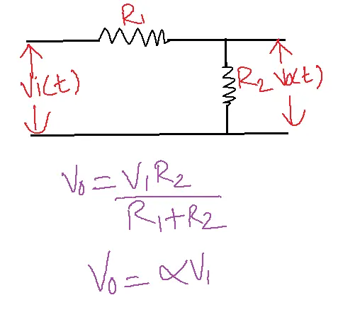
As a result, the input signal experiences an independent α times attenuation.
Table of Contents
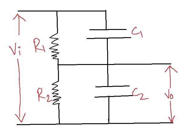
If the output of the attenuator is fed to an amplifier the input capacitance C2 of the amplifier will be shunting R2 of the attenuator shown below figure:
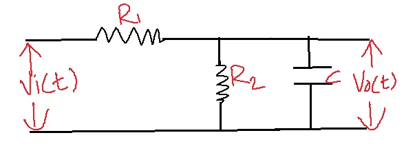
Now the attenuation factor is not independent of frequency. Using Thevenan’s theorem the equivalent model of the above circuit is
R=R1 // R2
The circuit’s rising time, tr = 2.2RC, is caused by huge resistor values. Let R1 = R2 = 1MΩ and C2= 12 PF then the rise time of the circuit is 13.2 µsec i.e., the rise time is much larger, and the capacitor takes a high time to charge and discharge because of that the shape of the output is altered which is unpredictable.
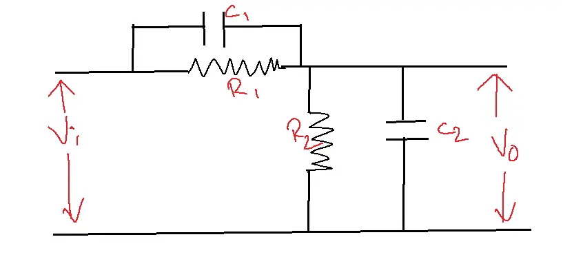
To compensate frequency effect in the above circuit connect one C1 capacitor parallel to the R1. The attenuation factor becomes insensitive to frequency when the bridge is balanced, with C1R1 matching C2R2.
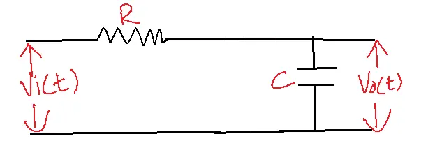
Rise Time
The time required for the circuit to increase its output from 10% to 90% of its maximum value.
Vo(t) = V [1-e-t/RC]
t=t1
t1=0.1RC
Rise time tr = 2.2 RC
Rise time tr = 0.35/Bandwidth.
Frequency-independent condition or response of step signal
t=0+, Vi =V
apply KVL for the above circuit
Vi =VC1 + VC2
VC1 = Q/C1
VC2 = Q/C2
V= q(C1+C2/C1C2)
V0 = ViR2/R1+R2
For a perfect attenuator, the output at t=0+ is the same as t=∞.
R1C1=R2C2
R1/R2 = C2/C1
Advantages of Attenuator:
1. Reduces Signal Strength: These circuits reduce signal strength, preventing damage to equipment or distortion.
2. Improves Signal Quality: These can improve signal quality by reducing noise and distortion.
3. Matches Impedance: These can match impedance between devices, ensuring maximum power transfer.
4. Provides Isolation: These circuits can provide isolation between devices, reducing interference.
5. Compact and Lightweight: These circuits are often compact and lightweight, making them easy to install.
Disadvantages of Attenuator:
1. Signal Loss: These circuits reduce signal strength, resulting in signal reduction.
2. Insertion Loss: These circuits introduce insertion loss, affecting signal quality.
3. Frequency Dependence: These circuits can be frequency-dependent, affecting signal quality at certain frequencies.
4. Temperature Sensitivity: These circuits can be temperature-sensitive, affecting performance.
5. Limited Dynamic Range: These circuits have a limited dynamic range, restricting their use in certain applications.
Applications
- Signal Level Adjustment: These circuits accurately lower digital signal amplitude or power to desired levels, preventing overloading and damage to sensitive devices.
- Pulse Shaping and Filtering: These circuits aid in pulse shaping and filtering in digital circuits, controlling pulse times, reducing noise, and enhancing signal quality.
- Impedance Matching: These circuits align impedance in digital circuits, minimizing signal reflections and maximizing power transfer, especially in high-frequency or high-speed systems.
- Testing and Calibration: These circuits create known signal levels for testing and calibrating digital circuits.
- Power Control and Protection: These circuits regulate power in digital circuits to prevent damage from excessive power levels.
- CRO has limitations concerning the amplitude of the signal to be displayed. The attenuated probe reduces the signal strength so it can be perfectly displayed on CRO.
- When the point at which the signal exists is at some distance from the CRO and it appears at a high impedance level the shielded cable is used to connect the signal to the CRO.
- This shielded cable has some capacitance of about 100 to 150 PF. [the capacitance value varies with the length of the cable].
- This capacitance with the input impedance of the source together will make it impossible to observe the waveform. To avoid that there is a variable capacitor C1 is used in the probe.
FAQs
1. What is an attenuator?
- It is a passive electronic device that reduces the amplitude or power of a signal without significantly distorting its waveform.
- It’s commonly used to adjust signal levels, match impedances, and protect circuits from excessive input power.
2. What are the different types of attenuators used in pulse & digital circuits?
- Common types include:
- Fixed attenuators: Provide a constant level of attenuation.
- Variable attenuators: Allow for adjustable attenuation levels.
- Step attenuators: Offer discrete attenuation steps for precise control.
- Programmable attenuators: Can be digitally controlled for automated adjustments.
3. How do attenuators work in pulse & digital circuits?
- Attenuators typically use resistive networks to dissipate a portion of the signal’s energy, reducing its amplitude.
- They can be designed for specific impedance matching and to maintain signal integrity in high-speed digital circuits.
4. What are the key parameters to consider when choosing an attenuator?
- Important factors include:
- Attenuation level: The amount of signal reduction required.
- Frequency range: The range of frequencies over which the attenuator operates effectively.
- Impedance: The input and output impedance of the attenuator should match the connected circuits.
- Power handling: The maximum power the attenuator can handle without damage.
- Accuracy and precision: The level of attenuation accuracy and repeatability required.
5. What are the common applications of attenuators in pulse & digital circuits?
- Attenuators are used in various applications:
- Adjusting signal levels: To prevent overload or match signal levels between different circuit stages.
- Testing and calibration: To provide precise signal levels for testing and calibration of equipment.
- Protecting sensitive circuits: To safeguard components from excessive input power.
- Improving signal-to-noise ratio: To reduce noise levels in communication systems.
- Impedance matching: To optimize power transfer between circuits with different impedances.