
A 3-phase Induction Motor is also called an Asynchronous motor.
Applications of electric motors:
Industrial loads, fan loads, pump loads, lifts, electric vehicles, and agriculture.
There are two types of electric motors. They are AC Motors and DC Motors.
AC Motors:
AC Motors are also classified into two types. They are
1. Synchronous motor.
2. Asynchronous motor is also called an induction motor.
Induction motors offer the advantage of being simpler and more durable in construction than synchronous motors, resulting in lower maintenance requirements.
Table of Contents
Principle of 3-phase Induction Motor:
The 3-phase Induction Motor works on the principle of mutual induction.
The 3-phase induction Motor has two parts stator and rotor.
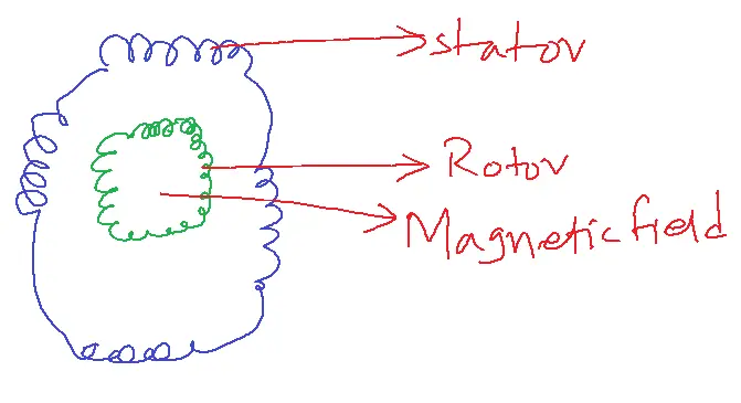
Stator having 3-phase balanced winding.
When a 3-phase balanced winding is excited by a 3-phase AC supply, the rotating magnetic field creates a stator winding (RMF).
Production of a rotating magnetic field
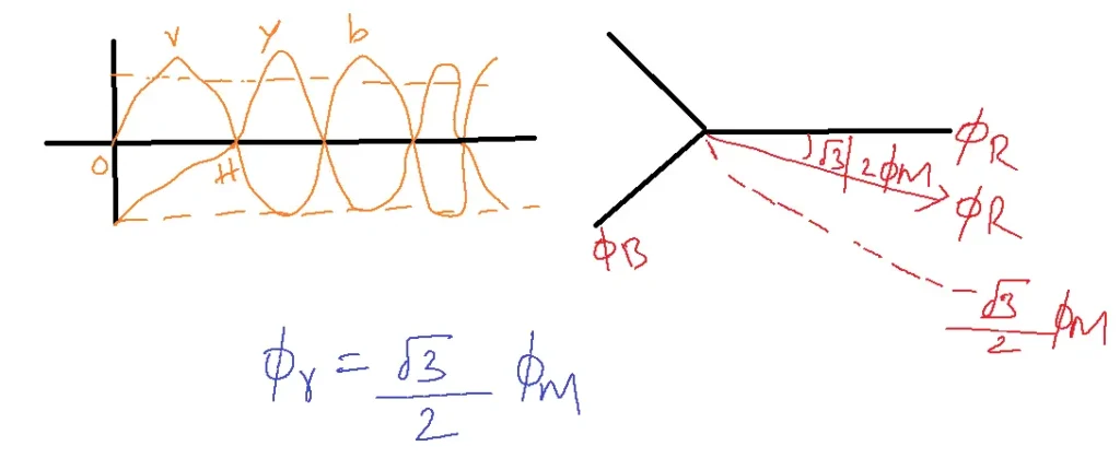
From the production of a rotating magnetic field, it can be concluded that the resultant flux vector will rotate in a clockwise direction with constant amplitude concerning the supply phase angle. This phenomenon is known as a rotating magnetic field. The speed of this magnetic field (RMFf) is known as synchronous speed (Ns).
The rotor conductors experience an induced electromotive force (emf) due to the cutting action of the magnetic field. This emf then passes current, creating rotor flux. The interaction between rotor flux and stator flux produces a torque. So the 3-phase induction motor is the self-starting motor.
Slip: The ratio of slip speed to synchronous speed or a difference between synchronous and rotor speed.
S = (Ns – N/Ns) x 100
Ns – synchronous speed based on supply frequency and stator poles.
Ns = 120f/P
f – supply frequency
P – Number of poles
N – actual speed of the motor
If Ns = N slip = 0, emf is not produced.
Based on rotor construction Induction motors are classified into 2 types:
1. Squiral Cage Induction Motor(SQIM)
2. Slipping or Wound rotor Induction Motor(SLIM)
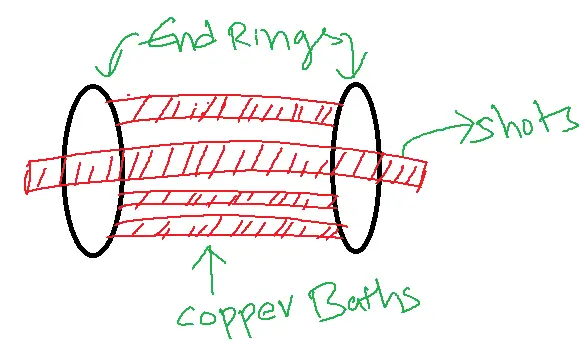
SQIM:
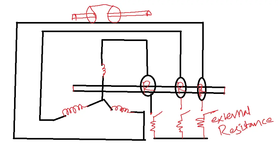
SLIM:
Comparison between SQIM and SLIM:
| SQIM | SLIM |
| In this rotor, Cu balls are inserted between two end rings. So these Cu balls are short-circuited by end rings, which gives cage structure. | In this rotor, a double layer 3-phase winding is wound and connected to slipping, and the other side of slipping connects to an external resistance across the shaft. |
| 90-95% of motors are SQIM because of its high starting torque and rugged construction. | 5-10% of motors are SLIM it has a feasibility of varying rotor resistance. So that torque can be varied. |
Losses and efficiency of 3-phase Induction Motor:
Electrical power inputs to the motor are classified as rotor input power or air gap power and stator loss. Rotor input power is further classified as Mechanical power and rotor Cu loss. Mechanical power is further classified as shift power and friction windage losses. Stator loss is further classified as stator Cu loss and iron and hysteresis losses.
Power flow diagram of 3-phase Induction Motor:
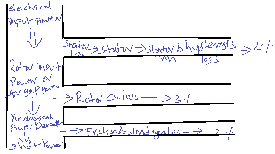
Stator losses: Losses occur in stators in two forms:
1. Stator Cu loss due to heat developed in stator windings.
2. Stator iron and hysteresis losses occur during the remaining power fed to the rotor. This rotor power fed into rotor Cu loss and mechanical power. This mechanical power meets friction and windage losses and the remaining power transfers to mechanical load.
nm = mechanical power(w or Kw) / mechanical power(w or Kw) + stator losses (w or Kw) + friction windage losses (w or Kw) + rotor Cu loss (w or Kw).
Starting Methods of 3-phase Induction Motor:
Torque = KE22R2/(K2+(xs2)2
E2 – rotor induced emf
R2 – rotor resistance.
According to torque expression, torque is proportional to the applied voltage square.
Torque = KSU22R2/(R22+(SH2)2
Starting a 3-phase Induction Motor:
If the applied voltage is high, torque will be high. High starting torque passes high starting currents it is almost 5-7 times the complete load current which damages stator windings. To reduce this high starting current some starting methods would be implemented in the induction motor but the 3-phase induction motor is self-activating.
1. DOL (Direct On Line) starter or DVOH starter
2. Auto transformed starter
3. Star delta starter
Starters of 3-phase Induction Motor:
There are two types of Induction Motors:
1. Spiral cage induction motor
2. Slip ring wounded induction motor or rotor rheostat motor

DOL Starter:
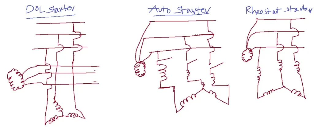
In DOL starter machines connect directly to the supply line. So supply voltage occurs across stator winding. To maintain low static currents supply voltage must be low. So this type of starter is referred to as a low-rated motor.
In the case of a rheostat starter, the rheostat is placed between supply and stator windings so some voltage drop appears between supply and stator windings.
As TαVs2, if the voltage drop is 50%, for example, if 50% of voltage decreases the starting currents and torque decrease by 25% because of TαVs2. This method has the disadvantage of high heating in resistors.
Auto stator supply voltage is varied through tappings or external windings, which decreases supply voltage. So torque and I(current) also decrease. This stator has fewer heating losses compared to the rheostat starter.
Star Delta Starter:
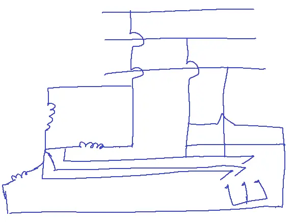
The Star Delta starter utilizes a star-delta connection to achieve a reduced starting current.
It establishes a star connection for starting and then transitions to a delta connection during normal operation.
In star connection, the preferred voltage decreases by 57.7% because in star V phase = VL/. When the voltage decreases to 1/3 of its original value, the torque decreases to 1/9, as torque is proportional to the square of the voltage (T ∝ V²). So that starting current also decreases but in running condition stator winding connects in correction and maintains rated voltage.
Example: A 3-phase induction motor runs at almost 1000 rpm at no load and 950 rpm at full load when supplied with a power 50 Hz free phase line. Calculate
1. How many poles are there in the motor?
2. % slip at full load.
3. fr at full load.
4. fr if slip is 10%
Solution:
Ns = 1000 rpm
N = 950 rpm
fs = 50 Hz
1. Ns= 120 X fs/P à P = 120 x 50/1000 = 6.
2. % S = Ns-N/Ns X 100 = 5%
3. fr = Sfs = 5/100 X 50 = 2.5 Hz
4. fr = Sfs = 10/100 X 50 5 Hz.
Related FAQs
Q1: What is the basic working principle of a 3-phase induction motor?
- A 3-phase induction motor operates on the principle of electromagnetic induction.
- Energizing the stator windings with a 3-phase AC supply generates a rotating magnetic field.
- This field induces currents in the rotor conductors, producing a magnetic field interacting with the stator field.
- This interaction generates torque, causing the rotor to rotate and follow the stator’s rotating magnetic field.
Q2: Why is the slip of a 3-phase induction motor important, and how does it affect motor performance?
- Slip is the difference between the synchronous speed (speed of the rotating magnetic field) and the actual rotor speed, expressed as a percentage.
- It’s crucial because it determines the amount of induced current and torque in the rotor.
- A higher slip means more current and torque, but also more losses.
- The slip varies with load, and understanding it is key to analyzing motor efficiency and speed-torque characteristics.
Q3: What is the equivalent circuit model of a 3-phase induction motor, and how is it used in network analysis?
- The equivalent circuit models the induction motor as a transformer with a rotating secondary (rotor).
- It consists of stator resistance and leakage reactance, rotor resistance and leakage reactance, and magnetizing reactance.
- Network analysis techniques applied to this model enable the calculation of parameters such as input current, power factor, torque, and efficiency across various operating conditions.
Q4: How does the V/f (voltage-frequency) control method work in 3-phase induction motors, and what are its advantages?
- V/f control maintains a constant ratio connecting the voltage and frequency applied to the motor.
- This ensures that the magnetic flux in the air gap remains almost constant, preventing magnetic saturation and maintaining optimal motor performance.
- It’s a popular method for speed control in induction motors, offering benefits like improved efficiency, wider speed range, and smoother operation.
Q5: What are the typical losses in a 3-phase induction motor, and how can they be minimized?
- The main losses are copper losses (I²R losses) in the stator and rotor windings, core losses (hysteresis and eddy current losses) in the iron core, and mechanical losses (friction and windage).
- These can be reduced by using high-conductivity materials for windings, laminating the core to decrease eddy currents, using high-quality bearings, and optimizing the motor design for efficient cooling.